Supporting device for laser marking of part
A technology of laser marking and supporting device, applied in the field of improvement of supporting device and supporting device, can solve the problems of low adjustment efficiency of parts and laser marking machine, increase the labor intensity of operators, affect the marking efficiency of parts, etc. Simple, easy to operate, and the effect of reducing the difficulty of adjustment
- Summary
- Abstract
- Description
- Claims
- Application Information
AI Technical Summary
Problems solved by technology
Method used
Image

Examples
Embodiment Construction
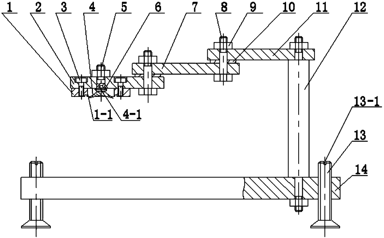
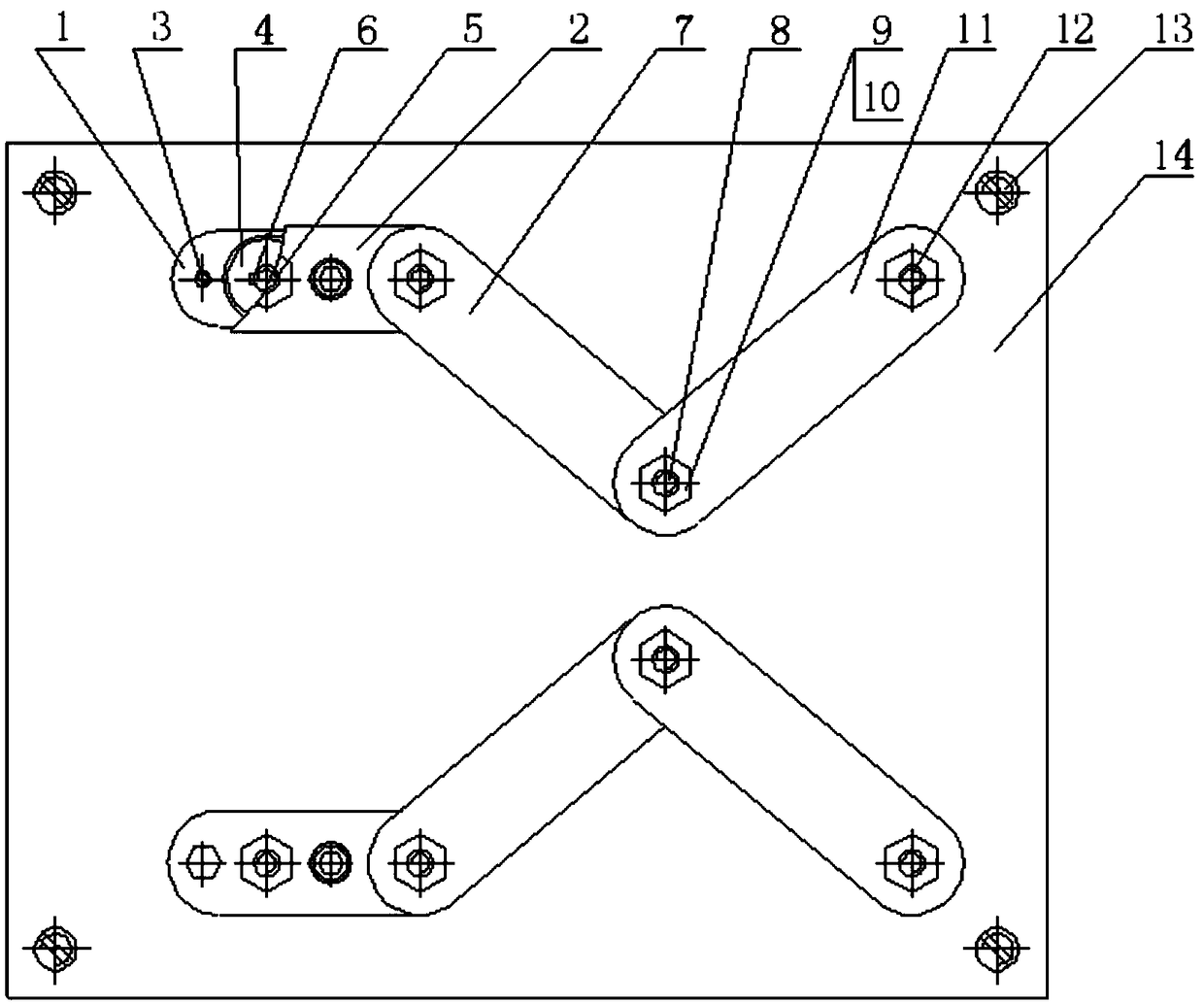
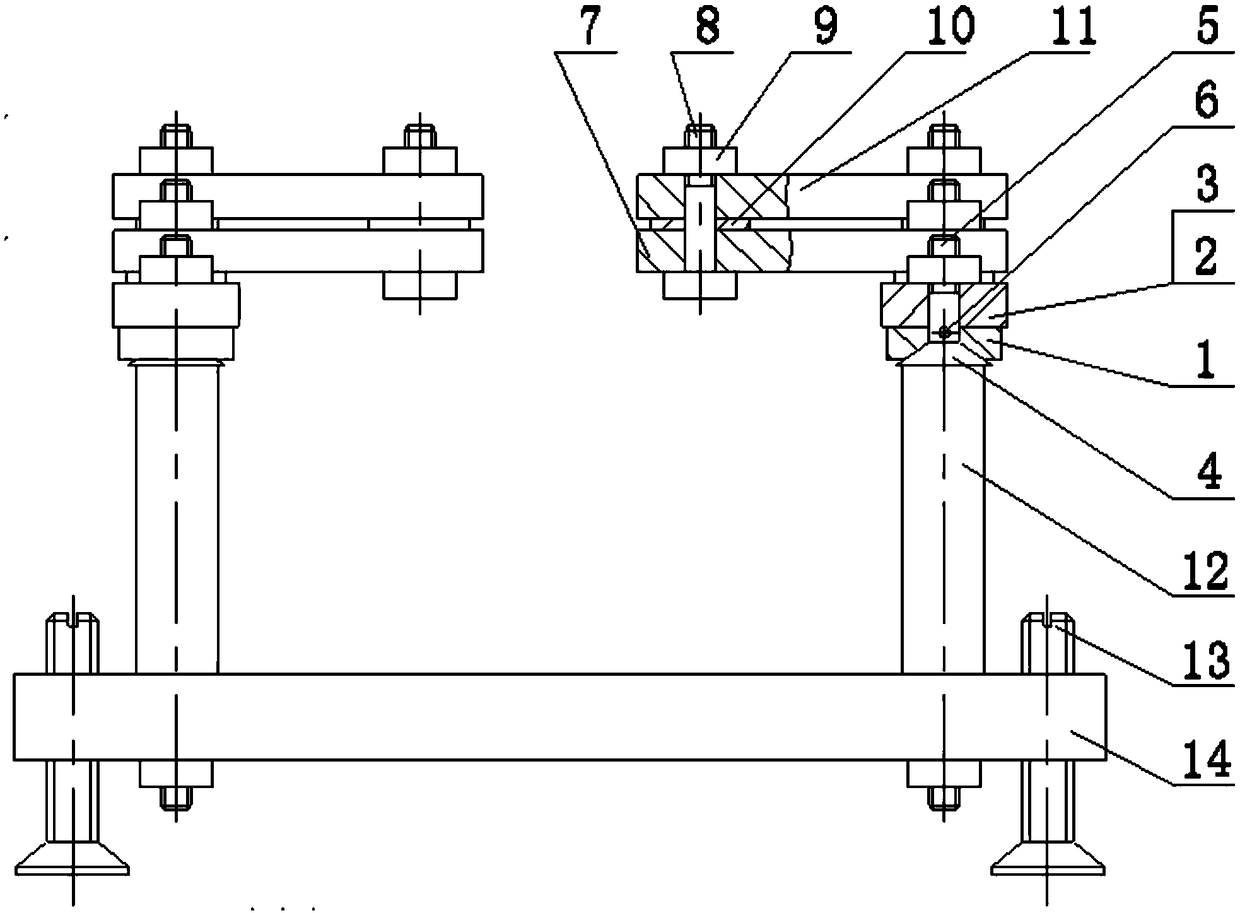
[0025] Below the present invention is described in further detail, as Figure 1 to Figure 3 A support device for laser marking of parts is shown, a support device for laser marking of parts, a number of anchor bolts 13 are arranged on the edge of the base 14; Two pillars 12 are fixedly connected, and each pillar 12 is movably connected to the first-stage rocker arm 11 through a fastening nut 9, and each first-stage rocker arm 11 is movably connected to the second-stage rocker arm 11 through a shaft bolt 8 and a fastening nut 9. A spacer 10 is provided between the arm 7, the first-stage rocker arm 11 and the second-stage rocker arm 7; each second-stage rocker arm 7 is movably connected to the third-stage rocker arm 2 by a shaft bolt 8 and a fastening nut 9 , a spacer 10 is provided between the second-stage rocker arm 7 and the third-stage rocker arm 2; each third-stage rocker arm 2 is fixedly connected to the electromagnetic chuck 1 by fixing bolts 3, and each third-stage rocke...
PUM
 Abstract
Description
Claims
Application Information
 - Generate Ideas
- Intellectual Property
- Life Sciences
- Materials
- Tech Scout
- Unparalleled Data Quality
- Higher Quality Content
- 60% Fewer Hallucinations
Browse by: Latest US Patents, China's latest patents, Technical Efficacy Thesaurus, Application Domain, Technology Topic, Popular Technical Reports.
© 2025 PatSnap. All rights reserved.Legal|Privacy policy|Modern Slavery Act Transparency Statement|Sitemap|About US| Contact US: help@patsnap.com