Automatic electronic-device assembling machine
A technology for automatic assembly machines and electronic devices, applied to assembly machines, metal processing, metal processing equipment, etc., can solve the problems of increased mold opening costs, cumbersome processing steps, and low production efficiency, and achieve simple structure, simplified assembly steps, The effect of improving market competitiveness
- Summary
- Abstract
- Description
- Claims
- Application Information
AI Technical Summary
Problems solved by technology
Method used
Image


Examples
Embodiment Construction
[0010] To further illustrate the various embodiments, the present invention is provided with accompanying drawings. These drawings are a part of the disclosure of the present invention, which are mainly used to illustrate the embodiments, and can be combined with related descriptions in the specification to explain the operating principles of the embodiments. With reference to these contents, those skilled in the art should understand other possible implementations and advantages of the present invention. Components in the figures are not drawn to scale, and similar component symbols are generally used to denote similar components.
[0011] The present invention will be further described in conjunction with the accompanying drawings and specific embodiments.
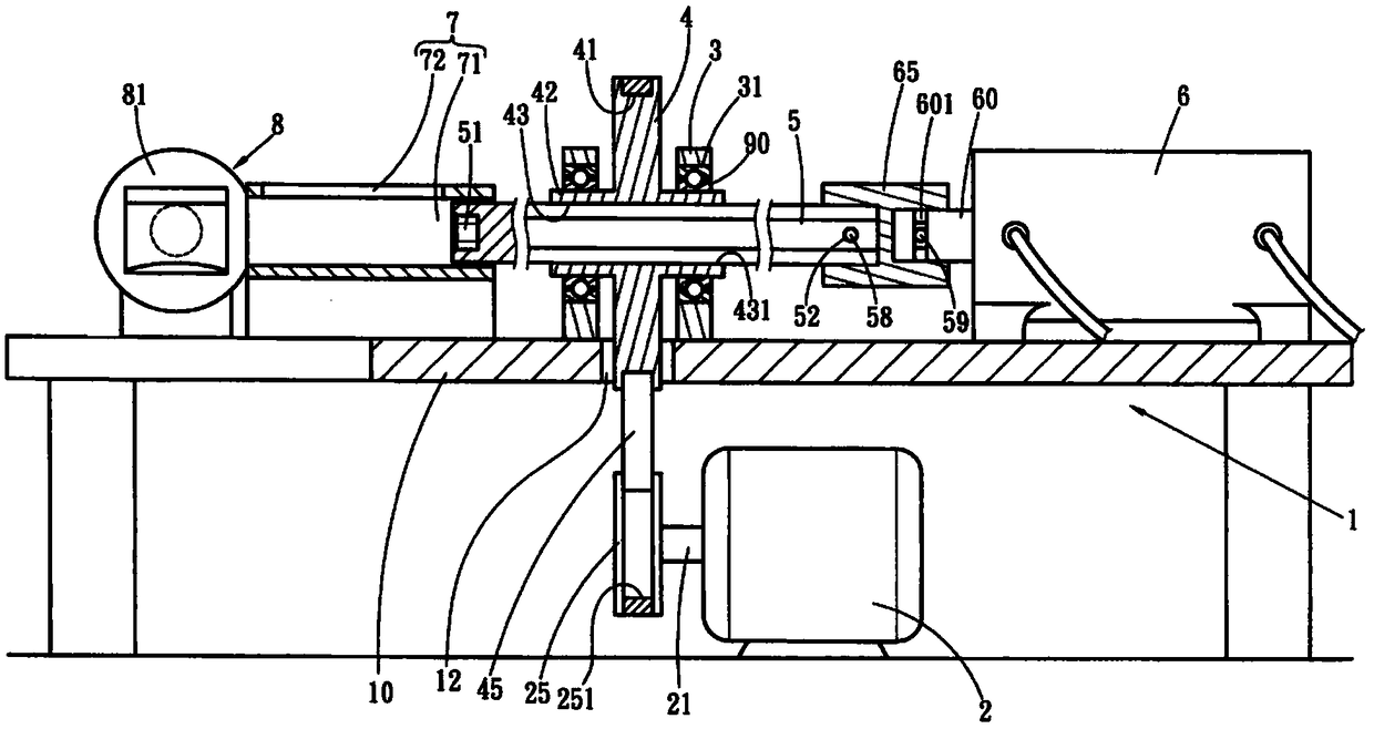
[0012] Such as figure 1 , 2 As shown, an automatic assembly machine for electronic devices provided in this embodiment includes a machine table 1 on which a motor 2, a support seat 3, an action valve 6, a guide seat 7...
PUM
 Abstract
Description
Claims
Application Information
 - Generate Ideas
- Intellectual Property
- Life Sciences
- Materials
- Tech Scout
- Unparalleled Data Quality
- Higher Quality Content
- 60% Fewer Hallucinations
Browse by: Latest US Patents, China's latest patents, Technical Efficacy Thesaurus, Application Domain, Technology Topic, Popular Technical Reports.
© 2025 PatSnap. All rights reserved.Legal|Privacy policy|Modern Slavery Act Transparency Statement|Sitemap|About US| Contact US: help@patsnap.com