Full-automatic stretching and cutting equipment for helical corrugated pipe

A technology of spiral bellows and cutting equipment, which is applied in metal processing equipment, other manufacturing equipment/tools, maintenance and safety accessories, etc., and can solve the problems of no effective protective measures at the cutting operation site, noise generated by cutting, metal particles splashing, etc. , to achieve the effect of reducing labor intensity and skill requirements of workers, preventing noise pollution and improving work efficiency

Inactive Publication Date: 2018-11-16
SHANGHAI LAINENG IND CO LTD
View PDF0 Cites 3 Cited by
  • Summary
  • Abstract
  • Description
  • Claims
  • Application Information

AI Technical Summary

Problems solved by technology

[0002] The stretching and cutting of the corrugated section of the stainless steel spiral corrugated pipe are the main processes of the end processing of the corrugated pipe. In the prior art, the stretching and cutting are all done manually in stages, and the operator directly contacts the clamping device and the cutting device, which is prone to accidents. Work-related accidents; and the fixed-length, clamping, and cutting operations are done manually, and the dimensional deviation and surface damage of the bellows caused by human errors cannot be avoided; the stretching and cutting operations are completed step by step, and each action is completed manually by the operator, which is inefficient , unable to work continuously; there are no effective protective measures at the cutting operation site, causing the metal particles generated by cutting to splash around, and cutting will also generate noise; therefore, there is a lack of a safe, accurate, efficient, continuous and environmentally friendly automatic operation equipment in the prior art

Method used


Image

  • Full-automatic stretching and cutting equipment for helical corrugated pipe

Examples


Embodiment Construction

[0022] The principles and features of the present invention are described below in conjunction with the accompanying drawings, and the examples given are only used to explain the present invention, and are not intended to limit the scope of the present invention.

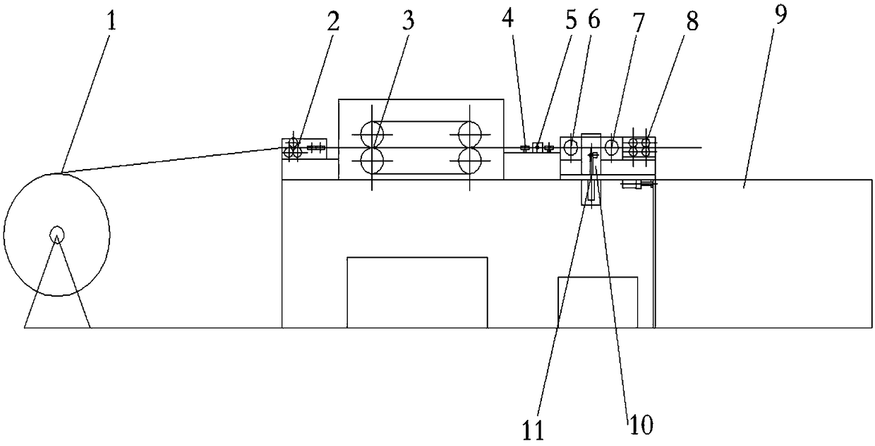
[0023] Such as figure 1 As shown, a spiral corrugated pipe automatic stretching and cutting equipment includes a corrugated pipe discharge rack 1 and a front guide device 2 connected to it in sequence, a conveying track 3, a rear guide device 4, a positioning system 5, and a front clamping mold base 6. The rear clamping mold base 7, the rear tensioning conveying device 8 and the receiving tray 9, a cutting tool 11 driven by a high-speed motor is arranged between the front clamping mold base 6 and the rear clamping mold base 7, and the The cutting tool 11 is integrally installed on a support base that can move up and down. The up and down movement of the support base is completed by the cylinder installed below the s...


PUM


Abstract

The invention relates to full-automatic stretching and cutting equipment for a helical corrugated pipe. The equipment comprises a corrugated pipe storing frame, a front guide device, a conveying crawler belt, a rear guide device, a locating system, a front clamping die base, a rear clamping die base, a rear tensioning and conveying device and a collecting disc, wherein the front guide device, theconveying crawler belt, the rear guide device, the locating system, the front clamping die base, the rear clamping die base, the rear tensioning and conveying device and the collecting disc are sequentially connected with the corrugated pipe storing frame. A laser locating system is adopted for accurately locating crest and trough positions and matched with the conveying crawler belt, accuracy ofcorrugated pipe locating is ensured, and the situation that during manual operation, the corrugated pipe is damaged by a clamping die piece is avoided. The cutting-off position of a cutting-off tool can be adjusted slightly in the axial direction, and the situation that the cutting position cannot be controlled during manual operation is avoided. The whole device is beneficial for improving the working efficiency, reducing labor intensity and lowering the technical requirement, and a safe, accurate, efficient, continuous and environment-friendly operation mode is provided.

Description

technical field [0001] The invention relates to the field of automatic cutting devices, in particular to a fully automatic stretching and cutting device for spiral corrugated pipes. Background technique [0002] The stretching and cutting of the corrugated section of the stainless steel spiral corrugated pipe are the main processes of the end processing of the corrugated pipe. In the prior art, the stretching and cutting are all done manually in stages, and the operator directly contacts the clamping device and the cutting device, which is prone to accidents. Work-related accidents; and the fixed-length, clamping, and cutting operations are done manually, and the dimensional deviation and surface damage of the bellows caused by human errors cannot be avoided; the stretching and cutting operations are completed step by step, and each action is completed manually by the operator, which is inefficient , unable to work continuously; there are no effective protective measures at ...

Claims


Application Information

Patent Timeline
Patent Type & Authority Applications(China)
IPC IPC(8): B23P23/04B23Q3/18B23Q11/08
CPCB23P23/04B23Q3/18B23Q11/08
Inventor 龚雪强庄惠青唐磊
Owner SHANGHAI LAINENG IND CO LTD
Why Eureka
Try Eureka