
Tyre vulcanizing unit, tyre vulcanizing machine comprising tyre vulcanizing unit and vulcanizing process

A tire vulcanization and tire technology, which is applied in the field of vulcanizing machines, can solve the problems of high unevenness on the inner surface of the tire and affect the quality of the tire, and achieve the effects of reducing the overall height, improving production efficiency, and saving the use area

Pending Publication Date: 2018-11-16
青岛海琅智能装备有限公司
View PDF0 Cites 3 Cited by
  • Summary
  • Abstract
  • Description
  • Claims
  • Application Information

AI Technical Summary

Problems solved by technology

[0004] Up to now, a few domestic companies have proposed bladder-free vulcanization and vulcanization machines, but their solution is to directly load raw tires into the mold, realize the positioning of the raw tire slits through mechanical devices, and enter high-temperature steam and high-pressure nitrogen for vulcanization. The unevenness of the inner surface of the tire produced by vulcanization is relatively high, and the bottom of the tire will accumulate condensed water due to the introduction of steam, which will affect the quality of the tire

Method used


Image

  • Tyre vulcanizing unit, tyre vulcanizing machine comprising tyre vulcanizing unit and vulcanizing process
  • Tyre vulcanizing unit, tyre vulcanizing machine comprising tyre vulcanizing unit and vulcanizing process
  • Tyre vulcanizing unit, tyre vulcanizing machine comprising tyre vulcanizing unit and vulcanizing process

Examples


Embodiment

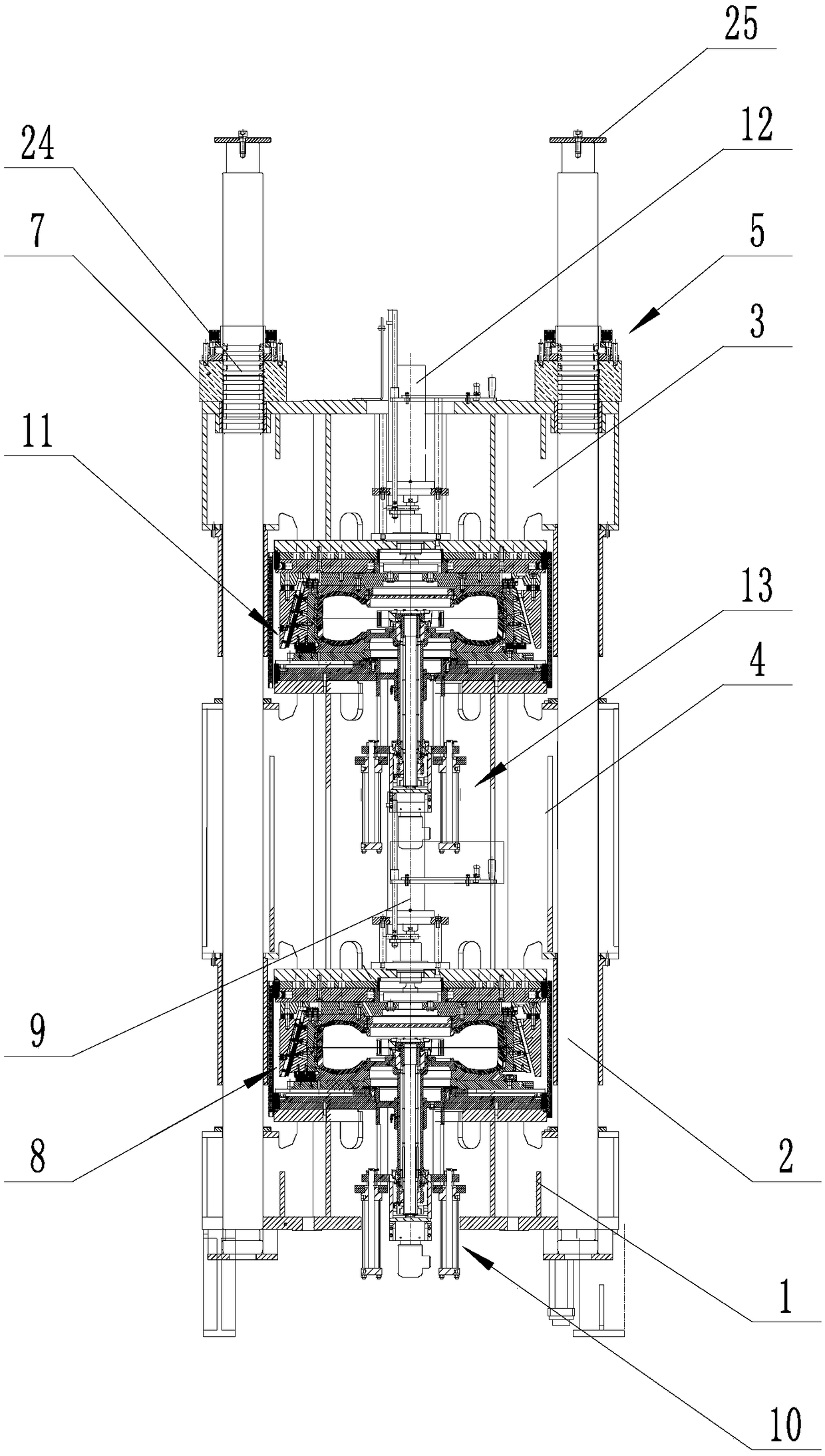
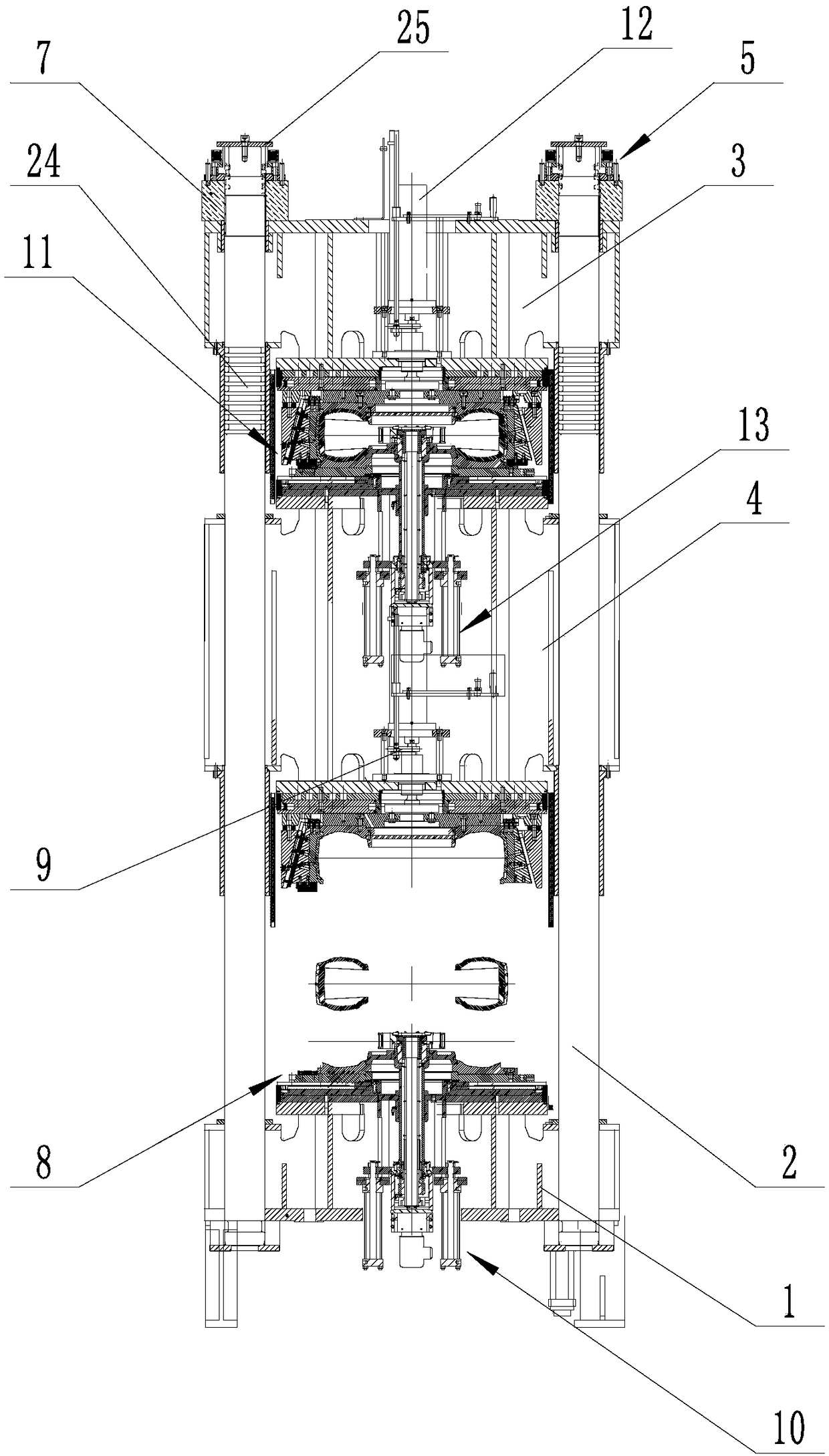
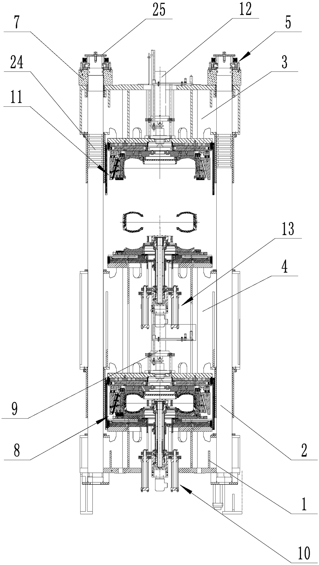
[0051] refer to Figure 1~3 , a tire vulcanization unit, including a base 1, and a guide column 2 fixedly connected to the base 1, the guide column 2 is connected with an upper movable beam 3 and a middle movable beam 4 from top to bottom, and the upper movable beam 3 There is a locking mechanism 5 for limiting the movement of the upper movable beam 3 along the guide column, and the upper movable beam 3 and the middle movable beam 4 are provided with a locking mechanism 5 for driving the upper movable beam 3 and the middle movable beam 4 to move along the guide column. The guide column 2 moves up and down the mold opening and closing cylinder group 6, the first movable mold assembly for vulcanizing tires is connected between the middle movable beam 4 and the base 1, the upper movable beam 3 and the middle movable beam 4 A second active mold assembly for vulcanizing tires is connected between them; an afterburner cylinder 7 for pressing down the first active mold assembly and t...


PUM


Abstract

The invention discloses a tyre vulcanizing unit, a tyre vulcanizing machine comprising the tyre vulcanizing unit and a vulcanizing process. The tyre vulcanizing unit comprises a base and a guide column which is fixedly connected onto the base, wherein the guide column is connected with an upper movable beam and a middle movable beam from top to bottom; a locking mechanism for limiting the upper movable beam to move along the guide column is arranged on the upper movable beam; opening-closing mould oil cylinder groups for driving the upper movable beam and the middle movable beam to move up anddown along the guide column are arranged on the upper movable beam and the middle movable beam; and a force applying oil cylinder for downwards extruding a first movable mould assembly and a second movable mould assembly is further arranged on the guide column in a sleeving mode. The tyre vulcanizing unit provided by the invention can simultaneously vulcanize two tyres; the tyre vulcanizing unitscan be assembled into a vulcanizing machine with a multi-mode vulcanizing form, so that the number of the tyre vulcanizing unit units can be confirmed according to practical site needs and processingneeds, and the tyre vulcanizing unit units are assembled, and therefore, the production efficiency of a vulcanizing workshop is greatly improved, and use area of the workshop is saved.

Description

technical field [0001] The invention belongs to the technical field of vulcanizing machines, and in particular relates to a tire vulcanizing unit, a tire vulcanizing machine containing the same and a vulcanizing process. Background technique [0002] At present, radial tires are mostly vulcanized by tire shaping vulcanizers in the form of bladders. This type of vulcanization of tires has obvious advantages and is widely accepted and used by countries all over the world. Internal temperature, during the vulcanization process, condensed water will accumulate at the bottom of the bladder, causing a large temperature difference in the internal temperature, which affects the quality of tire vulcanization; at the same time, the bladder has a limited lifespan and is a consumable product. The tire factory spends a relatively high amount of money on purchasing bladders every year. . [0003] Existing tire shaping vulcanizing machines are generally double-mode shaping vulcanizing mac...

Claims


Application Information

Patent Timeline
IPC IPC(8): B29D30/06B29C35/04
CPCB29C35/04B29D30/0601B29D30/065B29D30/0662B29D2030/067Y02W30/62
Inventor 孙贺王怀国高夫财刘培华李祥
Owner 青岛海琅智能装备有限公司
Learn More