Glass tube fixture, glass tube clamping ventilation head and vertical glass tube bulb-blowing machine

A technology of glass tube and bubble blowing machine, which is applied in glass forming, glass reshaping, glass manufacturing equipment, etc. It can solve the problems of clamping and sealing of glass tubes without using the principle of extrusion, and achieves convenient installation and disassembly as well as Replacement and maintenance, fewer parts used, and lower cost

Pending Publication Date: 2018-11-16
孔德训
View PDF9 Cites 0 Cited by
  • Summary
  • Abstract
  • Description
  • Claims
  • Application Information

AI Technical Summary

Problems solved by technology

[0004] The invention provides a glass tube clamp, which solves the technical problem that the prior art does not use the extrusion principle to realize the clamping and sealing of the glass tube

Method used


Image

  • Glass tube fixture, glass tube clamping ventilation head and vertical glass tube bulb-blowing machine
  • Glass tube fixture, glass tube clamping ventilation head and vertical glass tube bulb-blowing machine
  • Glass tube fixture, glass tube clamping ventilation head and vertical glass tube bulb-blowing machine

Examples


Embodiment 1

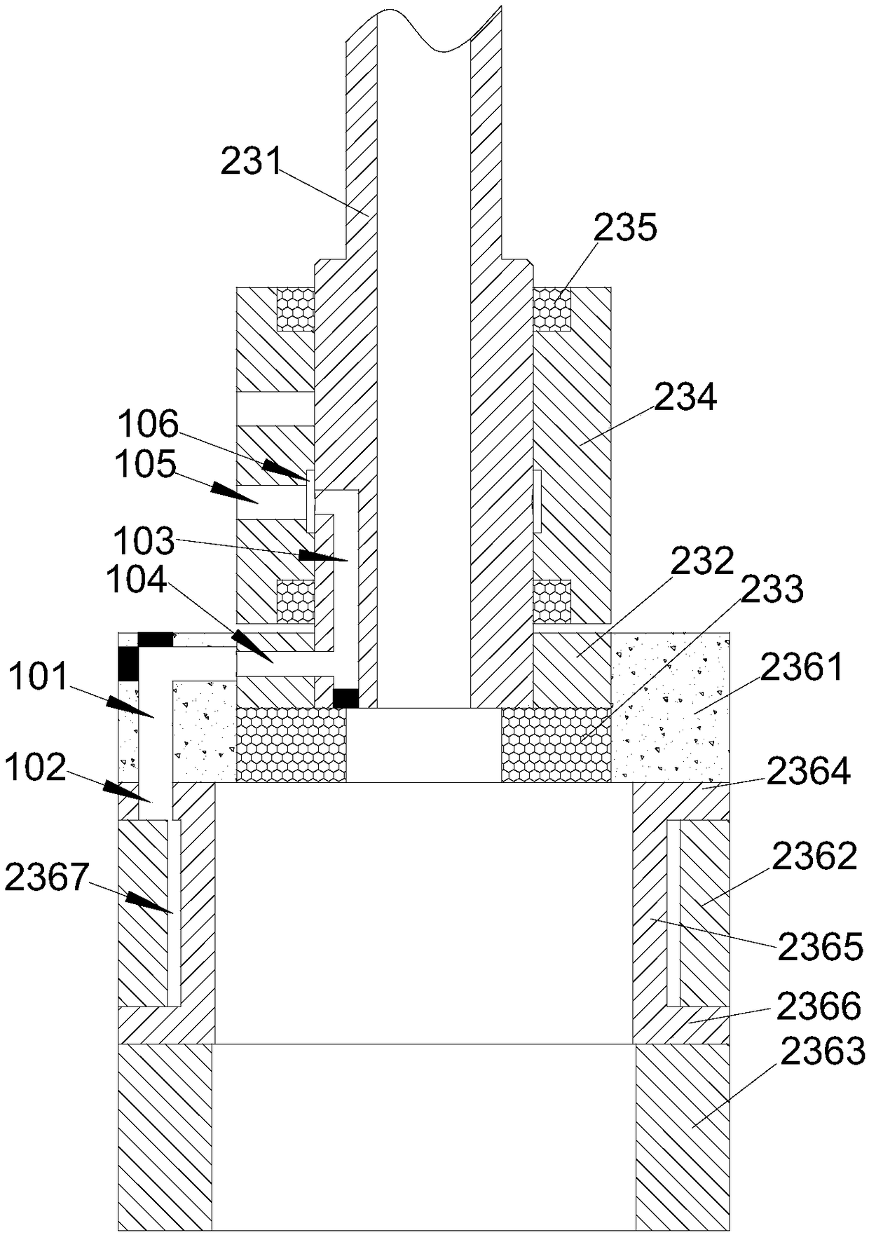
[0035] In this embodiment, a glass tube clamp is used to solve the problem of clamps that do not use extrusion to clamp the glass tube in the prior art, including an insertion barrel and an extrusion component, and the extrusion component is installed on the insertion barrel. When in use, the glass tube is inserted into the socket, and the extrusion part squeezes the glass tube so that the glass tube is pressed tightly in the socket. The structure is ingenious, and the parts are used less, which is more convenient for installation, disassembly, replacement and maintenance. , the cost is lower.

[0036] As a specific implementation of this embodiment, the extruding part in this embodiment can be an inflatable and deflated air bag, which is connected to the inner ring wall of the socket by screw locking or bonding. When it is pressed, it will squeeze the glass tube so that it is compressed into the socket.

[0037] As a best implementation mode of this embodiment, the inserting...

Embodiment 2

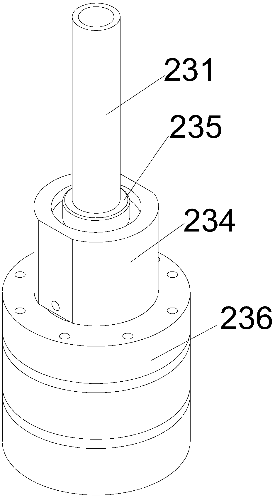
[0040] In this embodiment, a glass tube clamping ventilator head includes an air blowing pipe, an annular connecting flange A and the glass tube fixture in Embodiment 1, the main body of the above air blowing pipe is a straight pipe, and one end of the air blowing pipe is provided with a thickened structure A thickened end is formed, and the above-mentioned A ring-shaped connecting flange is coaxially arranged on the thickened end of the air blowing pipe. A fourth air channel is arranged on the wall body.

[0041] The inner wall of the upper cylinder of the above-mentioned glass tube fixture is provided with a B ring-shaped connecting flange coaxial with the upper cylinder and compatible with the above-mentioned A ring-shaped connecting flange. When installing, insert the above-mentioned A ring-shaped connecting flange into the above-mentioned upper cylinder and connect it to the above-mentioned B ring-shaped connecting flange through B screws. The inside of the glass tube cl...

Embodiment 3

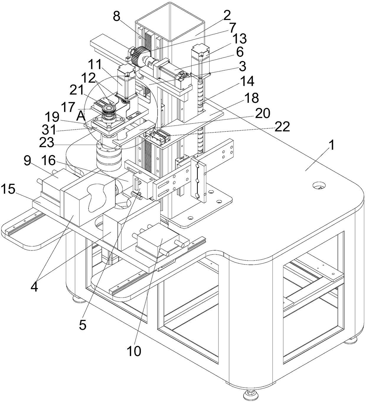
[0046] In this embodiment, a vertical glass tube bubble blowing machine includes a base, a column, a bracket, the glass tube clamping ventilator head in Embodiment 2, a mold and a flamethrower. The above-mentioned base is roughly in a frame structure, and the above-mentioned column is The strip-shaped square frame structure, the above-mentioned column is vertically installed on the upper end surface of the above-mentioned base.

[0047] The above-mentioned bracket is installed on the above-mentioned upright post by sliding up and down by the C guide rail slider pair, and a first driving part for driving the bracket to move up and down on the upright post is installed between the above-mentioned bracket and the upright post. Specifically, the guide rail of the above-mentioned C guide rail slider pair is vertically installed on the front side wall of the column, the slider of the C guide rail slider pair is installed on the above-mentioned bracket, and the above-mentioned first d...


PUM


Abstract

The invention relates to a glass tube fixture, a glass tube clamping ventilation head and a vertical glass tube bulb-blowing machine, and belongs to the technical field of glass tube processing. The glass tube fixture includes an insertion cylinder and an extrusion component. The extrusion component is arranged on the insertion cylinder. A glass tube is pressed tightly in the insertion cylinder toachieve sealing by an extrusion principle. The glass tube fixture has the advantages of ingenious structure, fewer employed parts, more convenient installation, disassembly, replacement and maintenance, and lower cost. The glass tube clamping ventilation head includes a gas blowing pipe, an A annular connecting flange and the glass tube fixture. The clamping and sealing of the glass tube fixtureare realized by an inflatable extrusion principle. The effect is good, and the glass tube clamping ventilation head has good land endurance performance. The vertical glass tube bulb-blowing machine includes base, a stand column, a bracket, the glass tube clamping ventilation head, a mould and a fire sprayer, is compact in structure, ingeniously adopts the inflatable principle to clamp the glass tube tightly, and has the advantages of good clamping and sealing effect, and good heat resistance effect.

Description

technical field [0001] The invention belongs to the technical field of glass tube processing, and in particular relates to a glass tube clamp, a glass tube clamping aerator head and a vertical glass tube blowing machine. Background technique [0002] A glass tube is a tubular structure made of glass, which is usually a straight tube, but in many cases, a glass vessel of other shape is required, which is usually made by inserting the glass tube at the wall It is heated and blown. [0003] With the development of science, some machines dedicated to glass tube blowing have appeared in the prior art. Glass tube clamps need to be used on this type of machine to clamp the glass tube when blowing air towards the glass tube. located on the machine. However, in the glass tube clamps in the prior art, it is usually necessary to use a plurality of parts to achieve the effect of clamping and sealing the glass tube respectively, and the principle of extrusion is not used to realize the...

Claims


Application Information

Patent Timeline
Patent Type & Authority Applications(China)
IPC IPC(8): C03B23/045C03B23/07
CPCC03B23/045C03B23/07
Inventor 孔德训
Owner 孔德训
Why Eureka
Try Eureka