Flat flame burner

A flat-flame burner and variable-section technology, applied in the field of furnaces and kilns, can solve the problems of reducing the recirculation zone, reducing the flat flame flame plate, and lowering the adjustment, so as to improve the combustion effect, improve the operation efficiency, and expand the scope of use. Effect

Inactive Publication Date: 2018-11-16
SHANGHAI INSTITUTE OF TECHNOLOGY
View PDF5 Cites 1 Cited by
  • Summary
  • Abstract
  • Description
  • Claims
  • Application Information

AI Technical Summary

Problems solved by technology

However, there are still the following problems: due to the relatively low adjustment of the flat flame burner, the centrifugal effect of the rotating air flow is not strong enough under low load, resulting in the reduction of the recirculation area and t

Method used


Image

  • Flat flame burner
  • Flat flame burner
  • Flat flame burner

Examples


Embodiment Construction

[0027] The present invention will be further described below in conjunction with specific embodiments and accompanying drawings, so as to help understand the content of the present invention.

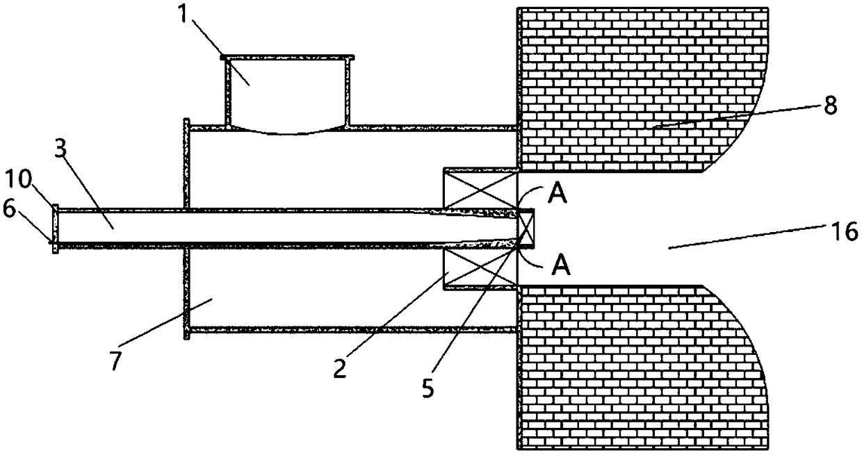
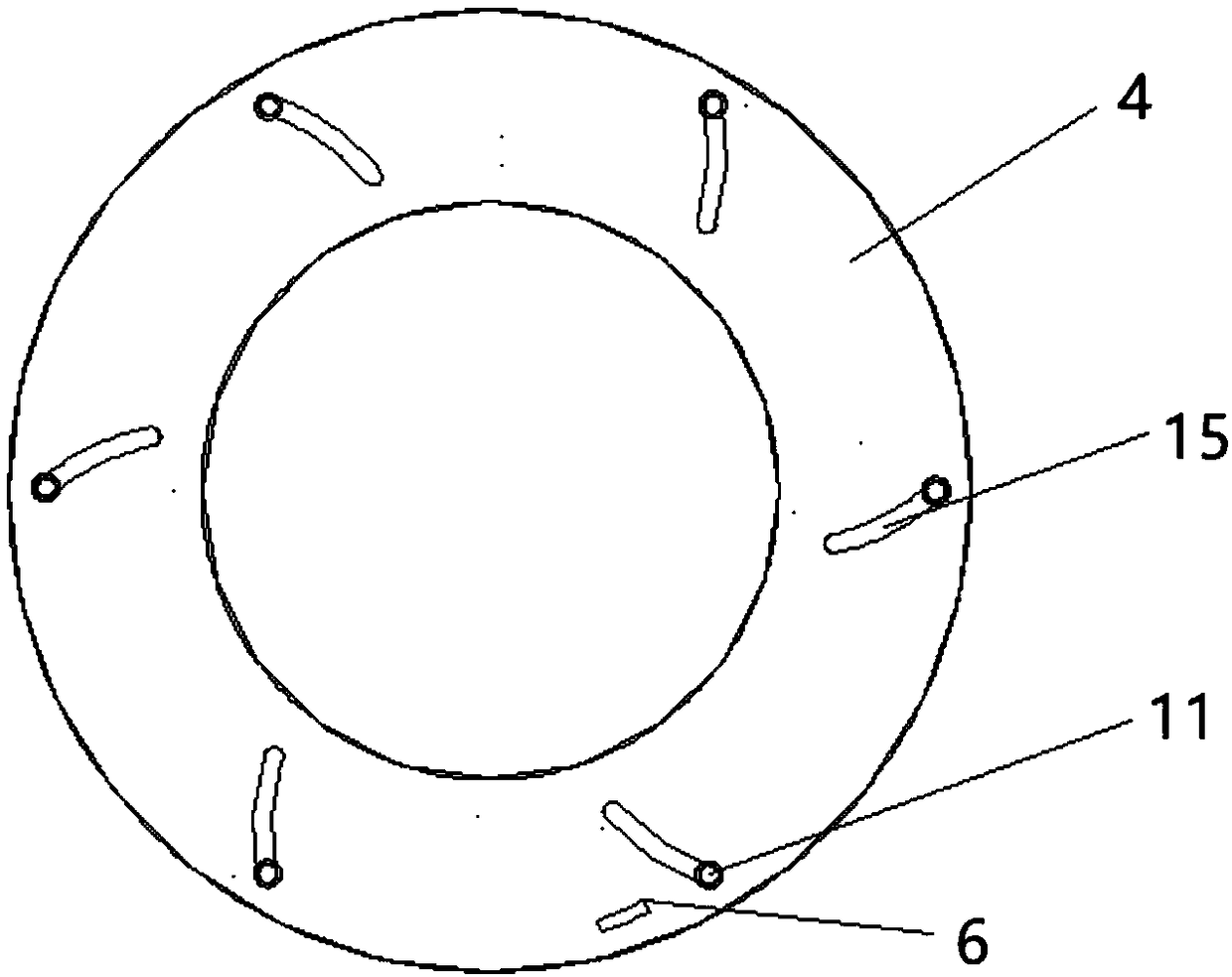
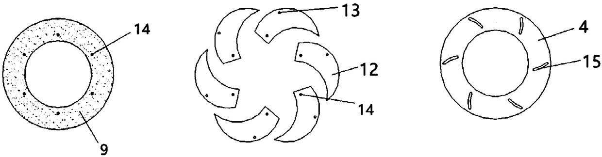
[0028] Such as Figure 1-9 As shown, the present invention discloses a flat flame burner, including: air intake pipe 1, gas intake pipe 3, swirler 2, burner housing 7, burner brick 8, variable section device 5, variable section control The rod 6 and the burner brick 8 form a combustion channel 16 with a gradually widening structure and communicate with the burner housing 7. The air intake pipe 1 is vertically arranged on the burner housing 7. The gas intake pipe 3 is a variable-section pipe and is sequentially arranged from the outside to the inside. The burner housing 7 and the swirler 2 extend into the combustion channel 16. The bottom of the gas inlet pipe 3 is provided with a variable-section device 5. The maximum cross-section of the variable-section device 5 is equal to the bottom...


PUM


Abstract

The invention discloses a flat flame burner. The flat flame burner comprises an air inlet pipe 1, an gas inlet pipe 3, a swirler 2, a burner shell 7, burner bricks 8, a variable cross section device 5and a variable cross section control rod 6, wherein the burner blocks 8 form a combustion channel 16 with a gradually-wide structure and communicates with the burner shell 7, the air inlet pipe 1 isvertically arranged on the burner shell 7, the gas inlet pipe 3 is a variable-cross-section pipe and sequentially passes through the burner shell 7 and the swirler 2 and extends into the combustion channel 16, the variable cross section device 5 is arranged at the bottom of the gas inlet pipe 3, the largest cross section of the variable cross section device 5 is equal to the cross section of the bottom of the gas inlet pipe 3, the gas inlet pipe 3 is arranged axial with the burner shell 7, the swirler 2, the variable-cross-section device 5 and the combustion channel 16, one end of the variable-section control rod 6 is connected with a blade driving ring 4 through a connecting rod, and the other end of the variable-section control rod 6 is arranged at the inlet of the gas inlet pipe 3, so that the variable-section control rod 6 is used for controlling the cross section area of the variable cross section device 5 to change the outlet of the bottom of the gas inlet pipe 3.

Description

technical field [0001] The invention belongs to the technical field of furnaces and kilns, in particular to a flat flame burner. Background technique [0002] The burner is the key equipment of the kiln, and its performance decisively affects the technical and economic indicators such as the output, quality, energy consumption, and environmental protection of the kiln. In new furnaces and kilns, the application of new high-efficiency burners and the improvement of the technical level of existing burners are of great significance for improving product quality, reducing energy consumption and protecting the environment. The flat-flame burner is a new type of burner developed. According to industrial practice, compared with the traditional diffusion burner, the flat-flame burner can increase the output by 10% to 20%, and save 15% % ~ 30% of the fuel. However, there are still the following problems: due to the relatively low adjustment of the flat flame burner, the centrifugal...

Claims


Application Information

Patent Timeline
IPC IPC(8): F23D14/24F23D14/46F23D14/84
CPCF23D14/24F23D14/46F23D14/84F23D2900/14001F23D2900/21
Inventor 罗雄辉钱惠国
Owner SHANGHAI INSTITUTE OF TECHNOLOGY
Why Eureka
Try Eureka