A method for obtaining the gas-liquid phase interface in a micron capillary channel

An acquisition method, capillary technology, applied in the direction of surface/boundary effects, instruments, measuring devices, etc., can solve the problems of inability to directly measure the contact angle, inability to observe the movement process of the phase interface, small field of view, etc.

Active Publication Date: 2019-12-10
INST OF MECHANICS - CHINESE ACAD OF SCI
View PDF3 Cites 0 Cited by
  • Summary
  • Abstract
  • Description
  • Claims
  • Application Information

AI Technical Summary

Problems solved by technology

[0007] But adopt above-mentioned two kinds of schemes all can't measure capillary number 10 -10 -5 and Bond number Bo-4 Dynamic contact angle under working conditions
[0008] In addition, in order to observe the contact angle, it is necessary to use a high-magnification microscope to obtain a magnified image, which means that the observation field of view is small
However, the dynamic displacement process means that the phase interface will move a certain distance, so high-magnification microscopes cannot observe the movement process of the phase interface
If a low magnification microscope is used to observe, the change of the position of the phase interface can be observed, but the phase interface cannot be observed, so the contact angle cannot be directly measured

Method used


Image

  • A method for obtaining the gas-liquid phase interface in a micron capillary channel
  • A method for obtaining the gas-liquid phase interface in a micron capillary channel
  • A method for obtaining the gas-liquid phase interface in a micron capillary channel

Examples


Embodiment Construction

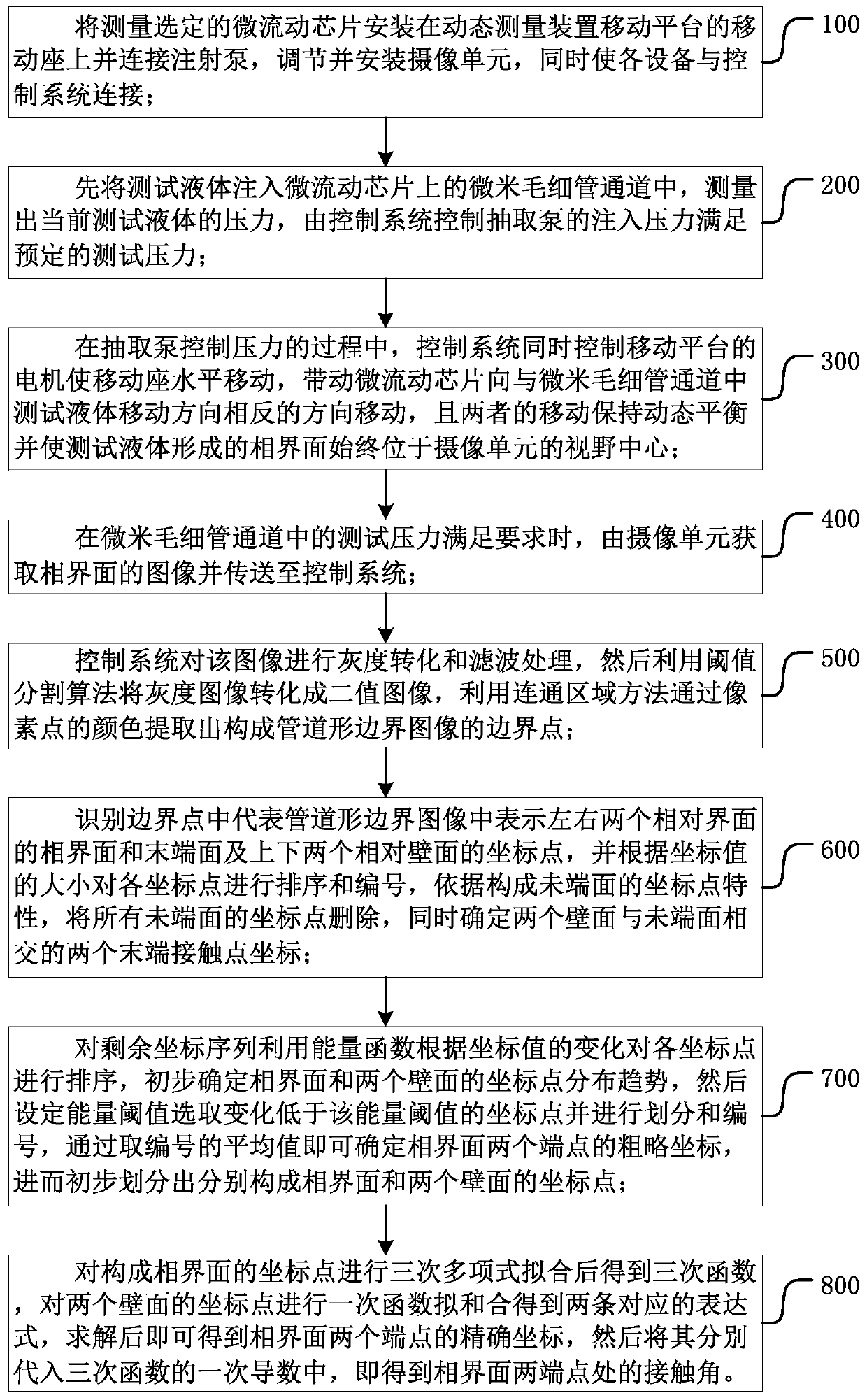
[0106] Such as figure 1 As shown, the present invention provides a method for obtaining a gas-liquid phase interface in a micron capillary channel, which generally includes the following steps:

[0107] Step 100, installing the microfluidic chip selected for measurement on the mobile seat of the mobile platform of the dynamic measurement device and connecting the syringe pump, adjusting and installing the camera unit, and connecting each device with the control system at the same time;

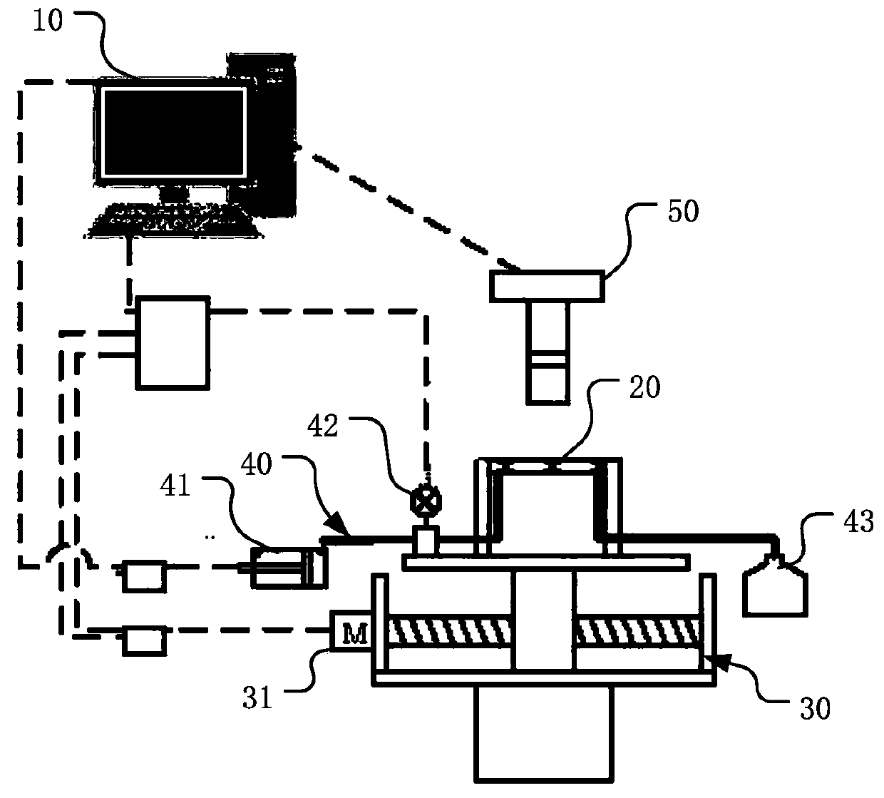
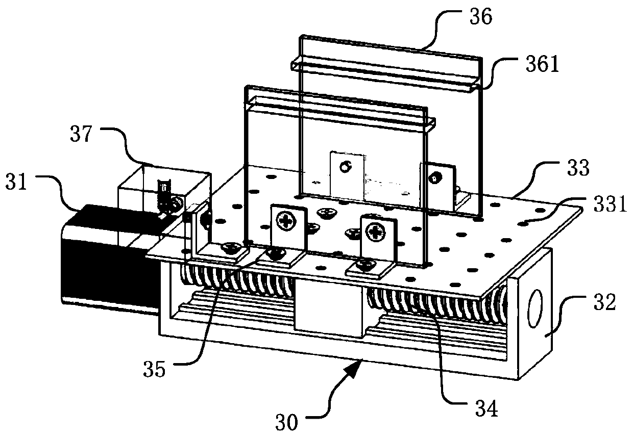
[0108] Such as figure 2 , 3 As shown in , 4 , the dynamic measurement device involved in this embodiment generally includes a microfluidic chip 20 , a pressure control pipeline 40 , a mobile platform 30 , a camera unit 50 and a control system 10 .

[0109] The microfluidic chip 20 is used for passing the test liquid, and is provided with a micron capillary channel 21; the specific microfluidic chip 20 may be a plate-shaped structure made of glass, organic material, or the like. The micron ...


PUM

PropertyMeasurementUnit
elastic modulusaaaaaaaaaa

Abstract

The invention provides a method for obtaining a gas-liquid phase interface in a micron capillary channel. The pressure or flow velocity of the gas-liquid two-phase flow process in a micron-scale capillary channel guide is controlled by a dynamic testing device, and the phase interface shape is obtained under the conditions of low capillary number and low Bond number for the first time. Phase interface shape calculation based on an image processing method is adopted for the first time, and the data processing efficiency and measurement accuracy are greatly improved. The invention also providesa variety of algorithms for control of two-phase flow pressure control and electric platform speed control, and the flexibility of actual operation is improved to meet the requirements of various working conditions.

Description

technical field [0001] The invention relates to the field of enhanced petroleum exploitation, in particular to a method for obtaining the gas-liquid dynamic displacement phase interface by using a dynamic measuring device equipped with a micron capillary channel. Background technique [0002] The mechanism of two-phase displacement in a single micron-scale capillary is the basis of two-phase displacement in porous media in natural environments. Two-phase displacement in porous media occurs in many industrial or natural processes, such as water in tight oil reservoirs. Gas drive, solution gas drive, water drive and other processes, the above-mentioned industrial processes are characterized by weak viscous force (the range of capillary number is 10 -10 <Ca<10 -5 ), weak gravity (Bond number Bo is less than 10 -4 ). The key factor affecting the displacement process is the capillary force, and the key parameter to calculate the capillary force is the contact angle betwe...

Claims


Application Information

Patent Timeline
Patent Type & Authority Patents(China)
IPC IPC(8): G01N13/00
CPCG01N13/00G01N2013/003
Inventor 雷达林缅江文滨曹高辉徐志朋李曹雄姬莉莉
Owner INST OF MECHANICS - CHINESE ACAD OF SCI
Why Eureka
Try Eureka