A photoionization detector system

A photoion detection and light source technology, applied in the field of photoion detection, can solve problems such as inconvenient calibration of photoion detectors, and achieve the effect of reducing labor costs and system downtime

Active Publication Date: 2018-11-16
JIAXING BROADSENS TECH LTD
View PDF7 Cites 4 Cited by
  • Summary
  • Abstract
  • Description
  • Claims
  • Application Information

AI Technical Summary

Problems solved by technology

[0003] The purpose of the present invention is to provide a photoion detection system to solve the problem of inconvenient calibration of existing photoion detectors

Method used


Image

  • A photoionization detector system
  • A photoionization detector system
  • A photoionization detector system

Examples


Embodiment Construction

[0040] The following examples are intended to illustrate the present invention, but not to limit the scope of the present invention.

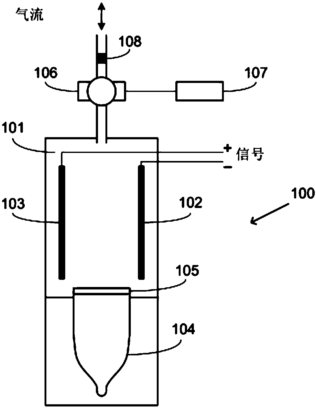
[0041] like figure 1 As shown, a PID system 100 based on the prior art has a measuring gas chamber 101, electrodes 102 and 103, a UV light source 104, a UV light window 105, an air pump module 106, a controller 107 and a dust filter 108 . The air pump module 106 is controlled by the controller 107 . A dust filter 108 is used to remove dust particles from the gas to be measured. Arrows show airflow direction at different times. The gas pump module 106 draws gas into the gas chamber 101 before the measurement begins. After that, the ultraviolet light source 104 is turned on, the gas molecules in the gas chamber are ionized, and electrical signals are monitored via the electrodes 102 and 103 . When performing the measurement of volatile organic compounds, air from the outside environment is pumped into the air chamber 101 . When the calibrat...


PUM


Abstract

The present invention discloses a photoionization detector system. The system comprises an ultraviolet light source used for providing ultraviolet radiation; a measurement gas chamber used for measuring volatile organic compounds from external environment gas and performing calibration measurement by utilizing one or more calibration gases; one or more calibration gas chambers holding the one or more calibration gases respectively; a plurality of gas pump modules controlling transmitting of the one or more calibration gases between the measurement gas chamber and the one or more calibration gas chambers; and a measurement circuit used for receiving electric signals generated by ultraviolet radiation photoionization of the one or more calibration gases in the measurement gas chamber. The system can significantly reduce the labor cost and system shutdown time during detection of volatile organic compounds, and can perform calibration automatically without the need of manual operation.

Description

technical field [0001] The invention relates to the technical field of photoion detection, in particular to a photoion detection system. Background technique [0002] Photoionization detectors (PIDs) are commonly used to detect volatile organic compounds (VOCs). It uses ultraviolet light (UV) to ionize gas molecules and measures the current signal caused by free electrons and ions. PID systems are extremely sensitive and can detect a wide range of organic compounds and other harmful chemicals at extremely low concentrations, such as parts per billion (ppb). The PID system has a relatively long service life and does not require frequent replacement. However, since PID systems are sensitive to external factors such as atmospheric pressure and ambient temperature, routine calibration is required to maintain measurement accuracy. For example, calibration is performed when moving a PID system from one place to another, or when the temperature changes outside a certain range. ...

Claims


Application Information

Patent Timeline
Patent Type & Authority Applications(China)
IPC IPC(8): G01N27/66
CPCG01N27/66G01N33/0006G01N33/0047
Inventor 张昶刘磊
Owner JIAXING BROADSENS TECH LTD
Why Eureka
Try Eureka