
Circuit board turning over tool

A technology for circuit boards and jigs, which is applied in the field of circuit board flipping jigs, can solve problems such as inability to recycle, fail to meet the rapid production of enterprises, waste resources, etc., and achieve the effects of improving production efficiency, avoiding bending, and reducing labor intensity

Inactive Publication Date: 2018-11-16
苏州艾可珐电子科技有限公司
View PDF0 Cites 3 Cited by
  • Summary
  • Abstract
  • Description
  • Claims
  • Application Information

AI Technical Summary

Problems solved by technology

Among them, manual use of high-temperature-resistant cloth to cover requires a lot of labor and wastes resources, which cannot be recycled and cannot meet the rapid production of enterprises.

Method used


Image

  • Circuit board turning over tool

Examples


Embodiment Construction

[0018] The present invention will be further described below in conjunction with the accompanying drawings and specific embodiments, so that those skilled in the art can better understand the present invention and implement it, but the examples given are not intended to limit the present invention.

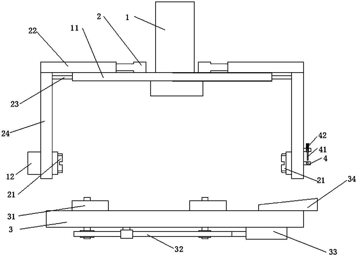
[0019] refer to figure 1 , a circuit board turning jig, including a turning grip and a positioning jig, the turning grip is set directly above the positioning jig, the turning grip is set on the lifting drive part 1, the The lifting drive part 1 drives the turning handle to move up and down. The positioning fixture includes a fixture plate 3 and a plurality of positioning components for positioning the circuit board. The positioning components are arranged on the fixture plate 3. The jig plate 3 is provided with grooves for shielding circuit boards or electronic components. The positioning component is connected to a positioning driving component, and the positioning driving compo...


PUM


Abstract

The present invention relates to the technical field of circuit board detection and in particular to a circuit board turning over tool. A groove on a tool plate is used for shielding a portion withoutthe need for high-temperature irradiation. The circuit board turning over tool can be recycled and is highly efficient in energy and friendly to environment. A turning over gripper clamps and turns over a circuit board so as to prevent the circuit board from being bent in transit, reduce the labor intensity of manual turnover, avoid manually turning over the cooled circuit board, and greatly improve production efficiency. A positioning driving component drives a plurality of positioning components to simultaneously position the circuit board, and has a synchronous clamping positioning function so as to facilitates the setting of the firmness of the circuit board in the tool plate and prevent slippage from affecting subsequent operations.

Description

technical field [0001] The invention relates to the technical field of circuit board detection, in particular to a circuit board flip jig. Background technique [0002] Many circuit boards on switching power supplies need to conduct high temperature resistance tests on both sides, but the test temperature is different between the side with circuit components and the other side. In the past, the method of shielding with high temperature resistant cloth was used to shield the side that does not need to be tested, and then High temperature detection, tear off the cover after high temperature detection and then test the other side. Among them, manual use of high-temperature-resistant cloth to cover requires a lot of labor, wastes resources, cannot be recycled, and cannot meet the rapid production of enterprises. Contents of the invention [0003] The technical problem to be solved by the present invention is to provide a circuit board turning jig with synchronous clamping and...

Claims


Application Information

Patent Timeline
Patent Type & Authority Applications(China)
IPC IPC(8): G01R31/28
CPCG01R31/2808G01R31/2817
Inventor 李郁夫
Owner 苏州艾可珐电子科技有限公司
Learn More