Laser transmitter

A technology of laser emission and laser, which is applied in the field of radar, can solve the problems that the spacing of lasers cannot be made very dense, the difficulty of production and adjustment, and the low space utilization rate, so as to reduce the size and weight of the system, low cost and miniaturization, The effect of size reduction

Active Publication Date: 2018-11-16
HESAI TECH CO LTD
View PDF6 Cites 2 Cited by
  • Summary
  • Abstract
  • Description
  • Claims
  • Application Information

AI Technical Summary

Problems solved by technology

The more columns, the more difficult the production and adjustment, the more complex the process, and the lower the production efficiency; the space utilization rate in the system is low, the focal plane is particularly crowded, the heat is large, and the heat is difficult to be exported, while other parts less fever
The layout

Method used


Image

  • Laser transmitter
  • Laser transmitter
  • Laser transmitter

Examples


Embodiment 1

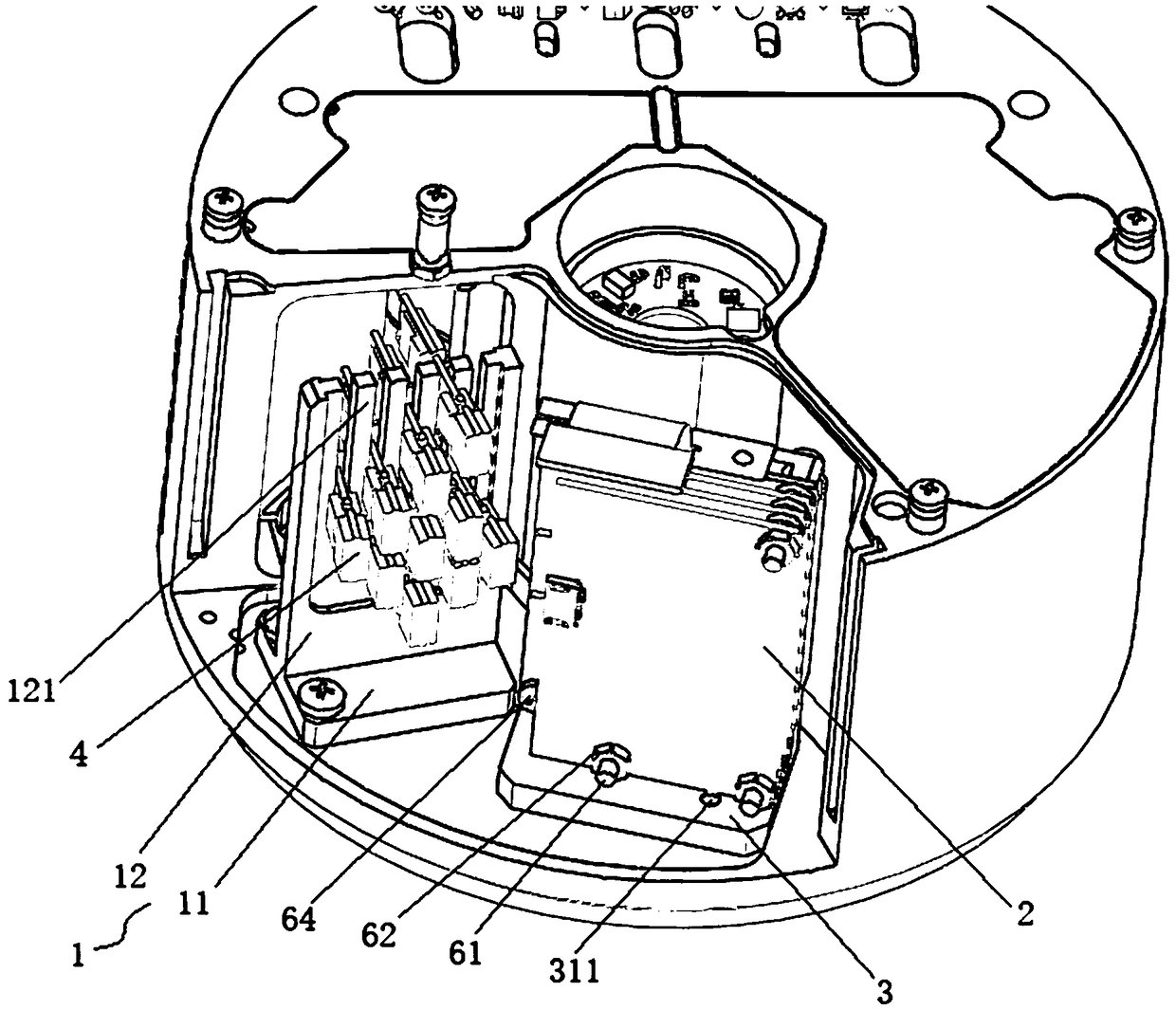
[0067] combine Figure 1 to Figure 5 As shown, a laser emitting device includes a laser bracket 1, a transmitting circuit group 2, a transmitting circuit bracket 3, at least one laser emitting board 4 and a plurality of flexible electrical connectors,

[0068] The laser bracket 1 and the transmitting circuit bracket 3 are arranged at intervals, the laser emitting board 4 is mounted on the laser bracket 1, and at least one laser 5 is arranged on the laser emitting board 4;

[0069] The transmitting circuit group 2 is mounted on the transmitting circuit bracket 3, and the transmitting circuit group 2 is connected to the laser emitting board 4 through the flexible electrical connector.

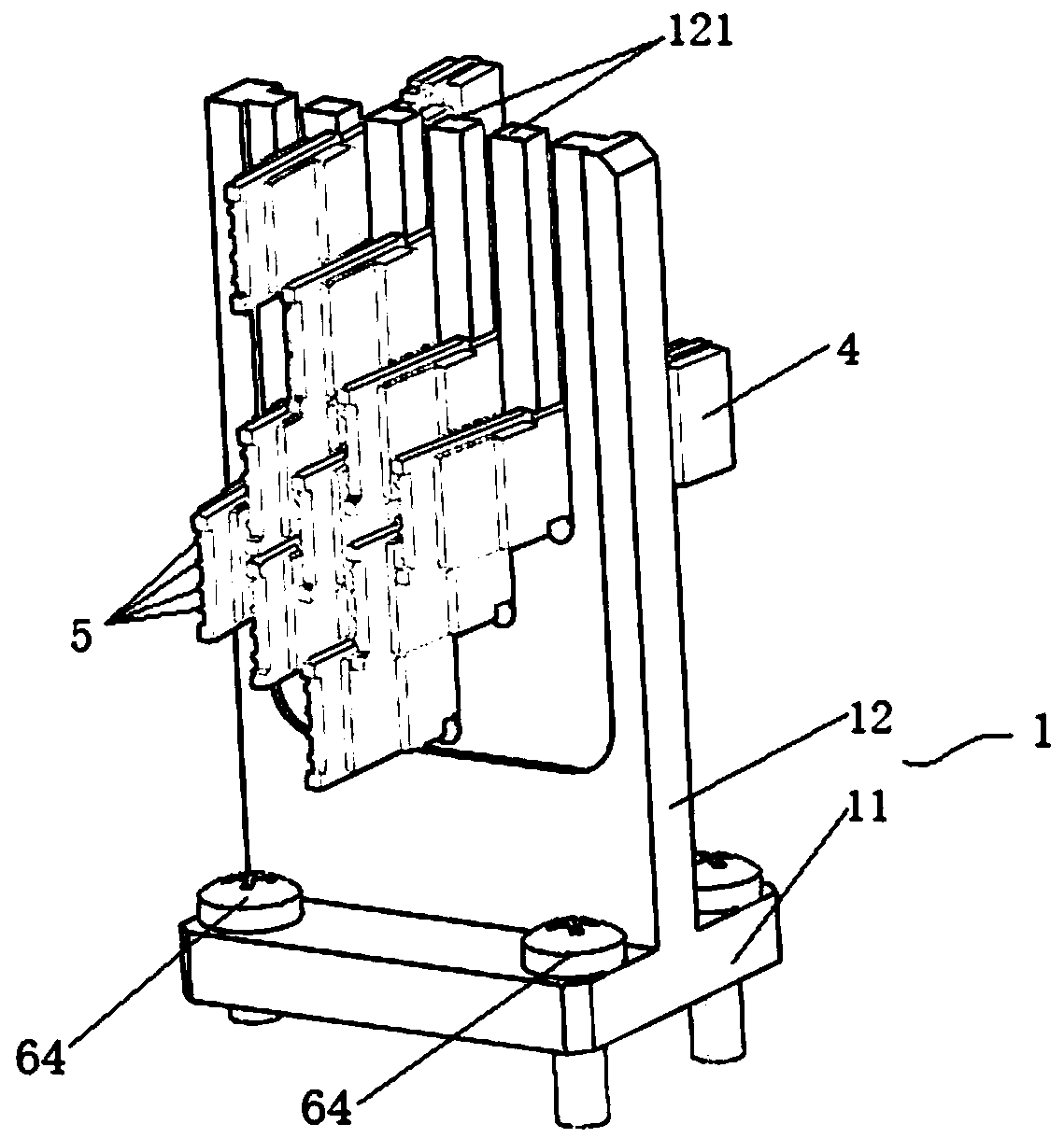
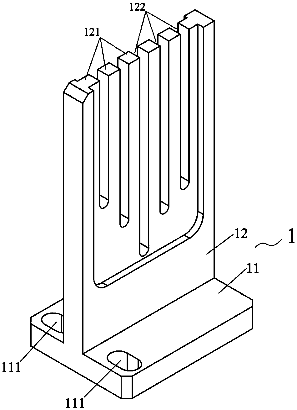
[0070] Such as figure 2 and image 3 As shown, the laser bracket 1 includes a first bottom plate 11 and a first side plate 12, the first bottom plate 11 is connected to the first side plate 12, and the first side plate 12 has a plurality of combs arranged side by side Teeth 121, a slot 122 fo...

Embodiment 2

[0112] refer to figure 1 and figure 2 As shown, a laser emitting device includes a laser bracket 1, a transmitting circuit group 2, a transmitting circuit bracket 3, at least one laser emitting board 4 and a plurality of flexible electrical connectors,

[0113] The laser bracket 1 and the transmitting circuit bracket 3 are arranged at intervals, the laser emitting board 4 is mounted on the laser bracket 1, and at least one laser 5 is arranged on the laser emitting board 4;

[0114] The transmitting circuit group 2 is mounted on the transmitting circuit bracket 3, and the transmitting circuit group 2 is connected to the laser emitting board 4 through the flexible electrical connector.

[0115] Such as Figure 6 As shown, the laser bracket 1 includes a first bottom plate 11 and a first side plate 12, the first bottom plate 11 is connected to the first side plate 12, and the first side plate 12 has a plurality of combs arranged side by side Teeth 121, a slot 122 for installin...

Embodiment 3

[0160] refer to figure 1 and figure 2 As shown, a laser emitting device includes a laser bracket 1, a transmitting circuit group 2, a transmitting circuit bracket 3, at least one laser emitting board 4 and a plurality of flexible electrical connectors,

[0161] The laser bracket 1 and the transmitting circuit bracket 3 are arranged at intervals, the laser emitting board 4 is mounted on the laser bracket 1, and at least one laser 5 is arranged on the laser emitting board 4;

[0162] The transmitting circuit group 2 is mounted on the transmitting circuit bracket 3, and the transmitting circuit group 2 is connected to the laser emitting board 4 through the flexible electrical connector.

[0163] refer to Figure 6As shown, the laser bracket 1 includes a first bottom plate 11 and a first side plate 12, the first bottom plate 11 is connected to the first side plate 12, and the first side plate 12 has a plurality of combs arranged side by side Teeth 121, a slot 122 for installin...


PUM


Abstract

The invention provides a laser transmitter which comprises a laser support, a transmitting circuit group, a transmitting circuit support, at least one laser transmitting plate and multiple flexible electric connectors. The laser support is arranged separate from the transmitting circuit support, and the laser transmitting plate is mounted on the laser support, and provide with at least one laser;and the transmitting circuit group is mounted on the transmitting circuit support, and connected with the laser transmitting plate via the flexible electric connectors. According to the laser transmitter, the laser transmitting plate and the transmitting circuit group are installed via the laser support and the transmitting circuit support respectively, so that space of a transmitting cabin of a laser radar is more flexible, and the laser radar is low in cost and mini; and the laser transmitting plate is connected with the circuit group via the flexible connectors, so that assembling is convenient.

Description

technical field [0001] The invention relates to the field of radar, in particular to a laser emitting device. Background technique [0002] As an important part of the intelligent vehicle environment perception hardware system, Lidar (LIDAR) undertakes important tasks such as roadside detection, obstacle recognition, and real-time localization and mapping (SLAM) in automatic driving. The LIDAR system consists of a laser emitting system and a receiving system. The laser transmitter system generates and emits light pulses, hits the object and reflects back, and is finally received by the receiver. The receiver accurately measures the travel time of the light pulse from when it is emitted to when it is reflected back. Because light pulses travel at the speed of light, the receiver will always receive the previous reflected pulse before the next one is sent. Given that the speed of light is known, travel time can be converted into a measure of distance. LiDAR can accurately ...

Claims


Application Information

Patent Timeline
IPC IPC(8): G01S7/484
CPCG01S7/484
Inventor 王红光向少卿
Owner HESAI TECH CO LTD
Why Eureka
Try Eureka