Wearing-resistant ultrasonic thickness meter with high testing precision

A detection accuracy and anti-wear technology, applied in the direction of sound wave re-radiation, radio wave measurement system, instrument, etc., can solve the problems of too far difference between the measurement position and the target measurement position, reduce the measurement accuracy, reduce the detection accuracy, etc., and achieve detection The accuracy is safe and reliable, the detection accuracy is improved, and the detection accuracy is high.

Active Publication Date: 2018-11-16
鼎立九州质检技术服务有限公司
View PDF8 Cites 8 Cited by
  • Summary
  • Abstract
  • Description
  • Claims
  • Application Information

AI Technical Summary

Problems solved by technology

[0003] In the measurement process of the existing ultrasonic thickness gauge, when the measured value is unstable, the 300mm multi-point measurement method is usually used, that is, with one measurement point as the center, multiple measurements are made in a circle with a diameter of about 30mm, and the smallest The value is the thickness value of the workpiece to be measured. When using this method to measure, the position of the probe needs to be adjusted. However, during the movement of the probe, the surface of the probe is easy to wear with the workpiece, resulting in an increase in the surface roughness of the probe after long-term use, resulting in a decrease in sensitivity and a decrease in sensitivity. Measurement accuracy, not only that, during the movement of the probe, the angle between the probe angle and the surface of the workpiece changes, which further reduces the detection accuracy, and during the detection process, the probe is prone to a large position shift, resulting in the actual measurement position The distance from the target measurement position is too far, so that the actual measured value has a large deviation, which reduces the practicability of the existing ultrasonic thickness gauge

Method used


Image

  • Wearing-resistant ultrasonic thickness meter with high testing precision
  • Wearing-resistant ultrasonic thickness meter with high testing precision
  • Wearing-resistant ultrasonic thickness meter with high testing precision

Examples


Embodiment Construction

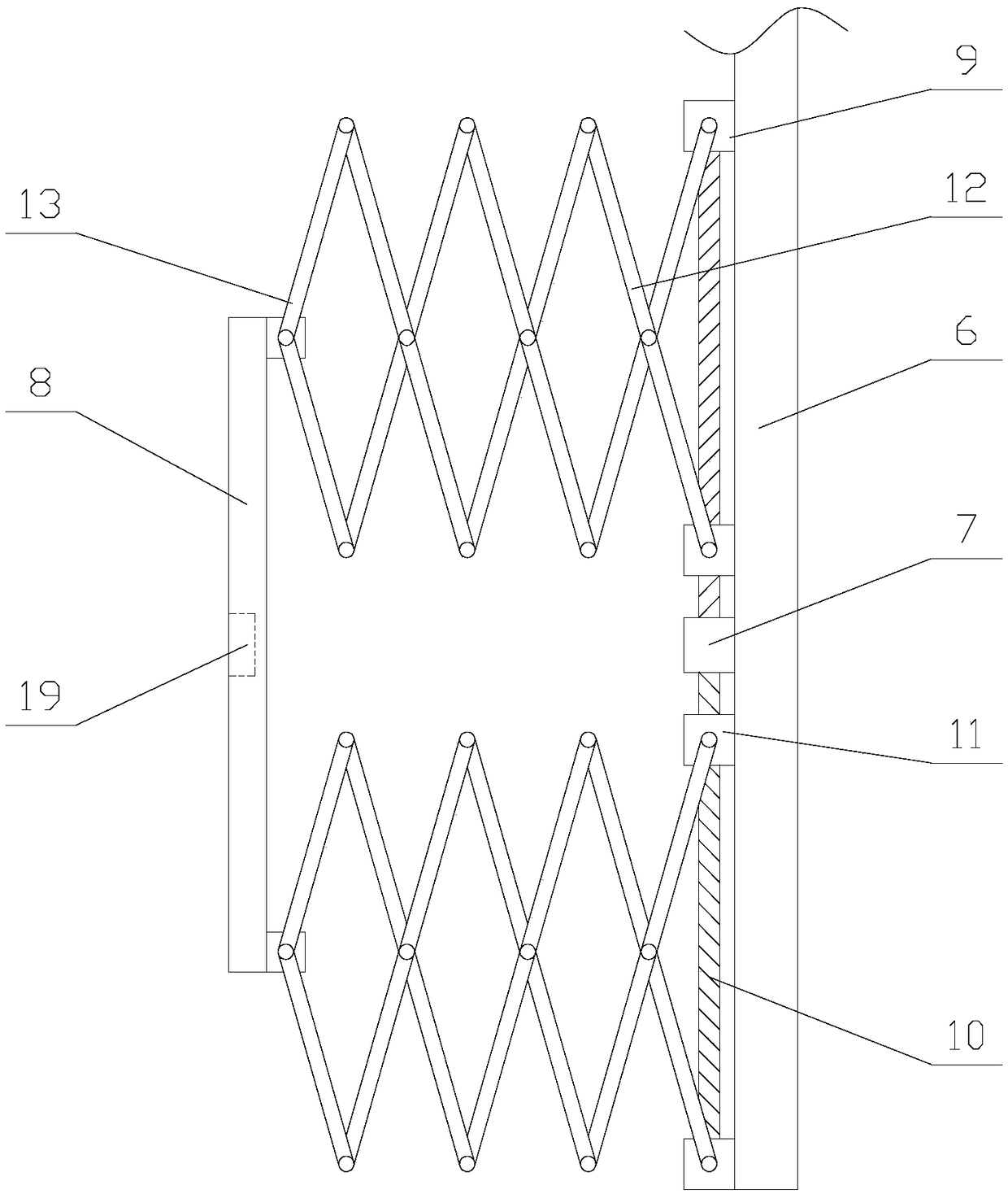
[0025] The present invention is described in further detail now in conjunction with accompanying drawing. These drawings are all simplified schematic diagrams, which only illustrate the basic structure of the present invention in a schematic manner, so they only show the configurations related to the present invention.

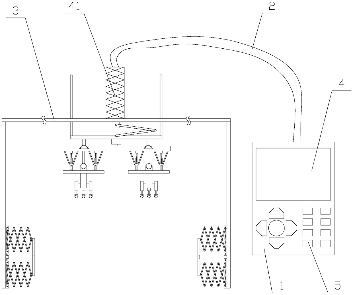
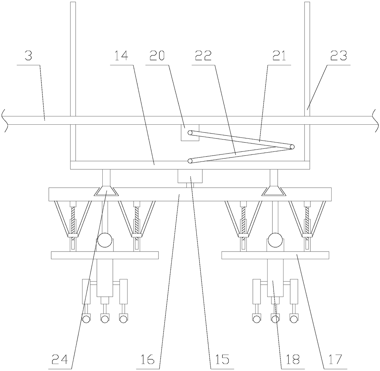
[0026] Such as figure 1 As shown, a wear-resistant ultrasonic thickness gauge with high detection accuracy includes a host 1, a connecting wire 2, an operating rod 41, a flat plate 3, a detection mechanism and two fixing mechanisms. The host 1 is provided with a display screen 4 and a plurality of buttons 5, the host 1 is provided with a PLC, the buttons 5 and the display screen 4 are electrically connected to the PLC, the host 1 is connected to the operating rod 41 through the connecting line 2, and the operating rod 41 is fixed on the flat panel 3, the detection mechanism and the fixing mechanism are located on the other side of the flat panel 3, and the tw...


PUM


Abstract

The invention relates to a wearing-resistant ultrasonic thickness meter with high testing precision. The ultrasonic thickness meter comprises a host machine, a connecting line, an operating lever, a flat plate, a testing mechanism and two fixing mechanisms. The fixing mechanism comprises a fixed plate, a first motor, clamping plates and two telescopic assemblies. The telescopic assembly comprisesa bearing, a first driving shaft, a moving block, a telescopic rack and two first connecting rods. The testing mechanism comprises a moving assembly, a movable board, a second motor, a turntable and two testing assemblies. The testing assembly comprises an adjusting unit, an adjusting plate, a probe and a plurality of testing units. The wearing-resistant ultrasonic thickness meter with high testing precision makes the two clamping plates fix a workpiece through the fixing mechanisms, thereby preventing relatively large-distance offset of a probe in a testing process, and ensuring smooth testing. Furthermore, in a process of driving the probe to perform rotating testing through the testing mechanism, the angle of the probe is adjusted and testing precision is improved; and furthermore wearing caused by contact between the probe and the workpiece is prevented, thereby prolonging service life of the equipment.

Description

technical field [0001] The invention relates to the field of ultrasonic detection equipment, in particular to an anti-wear ultrasonic thickness gauge with high detection accuracy. Background technique [0002] The ultrasonic thickness gauge measures the thickness according to the principle of ultrasonic pulse reflection. When the ultrasonic pulse emitted by the probe passes through the object to be measured and reaches the interface of the material, the pulse is sent back to the probe. By accurately measuring the propagation time of the ultrasonic wave in the material, the Determine the thickness of the material being measured. Ultrasonic thickness gauges can measure the thickness of various pipes and pressure vessels in production equipment, detect their degree of thinning after being corroded during use, and can also accurately measure various plates and various processed parts. [0003] In the measurement process of the existing ultrasonic thickness gauge, when the measu...

Claims


Application Information

Patent Timeline
Patent Type & Authority Applications(China)
IPC IPC(8): G01S15/10G01S7/521
CPCG01S7/521G01S15/101
Inventor 吴键斌
Owner 鼎立九州质检技术服务有限公司
Why Eureka
Try Eureka