Electric connector

A technology of electrical connectors and electrical contacts, which is applied in the direction of connections, circuits, and parts of connection devices, etc., can solve problems such as crosstalk, impedance changes, high-speed signal loss, etc., to reduce crosstalk, suppress capacitance reduction, Effect of reducing transmission loss

Active Publication Date: 2018-11-16
DEYI PRECISION ELECTRONIC IND CO LTD PANYU
View PDF4 Cites 16 Cited by
  • Summary
  • Abstract
  • Description
  • Claims
  • Application Information

AI Technical Summary

Problems solved by technology

[0003] However, the fixed part is buried in the insulating block, the elastic arm is exposed to the air, and when the signal is transmitted from the fixed part to the elastic arm, since the dielectric constant of the air is smaller than that of the insulating block, the ground terminal and the adjacent differential signal The capacitance between the terminals is reduced due to the reduction of the dielectric constant, resulting in a change in the impedance between the ground terminal and the adjacent differential signal terminal, resulting in loss of high-speed signals and crosstalk

Method used


Image

  • Electric connector
  • Electric connector
  • Electric connector

Examples


Embodiment Construction

[0026] In order to facilitate a better understanding of the purpose, structure, features, and effects of the present invention, the present invention will now be further described in conjunction with the accompanying drawings and specific embodiments.

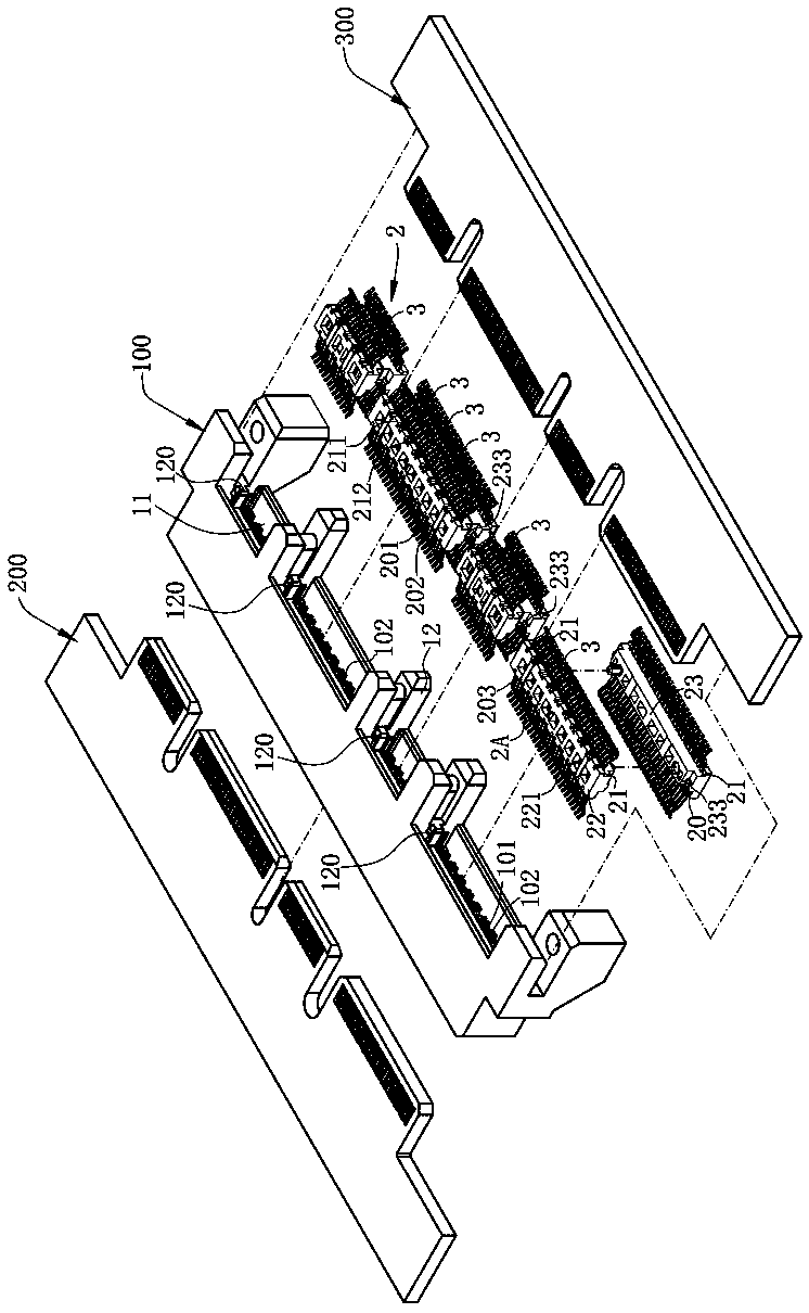
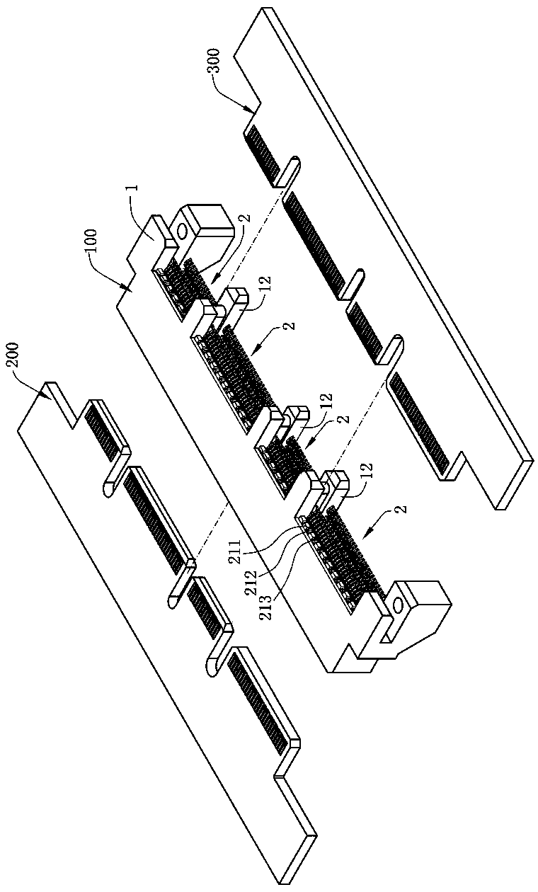
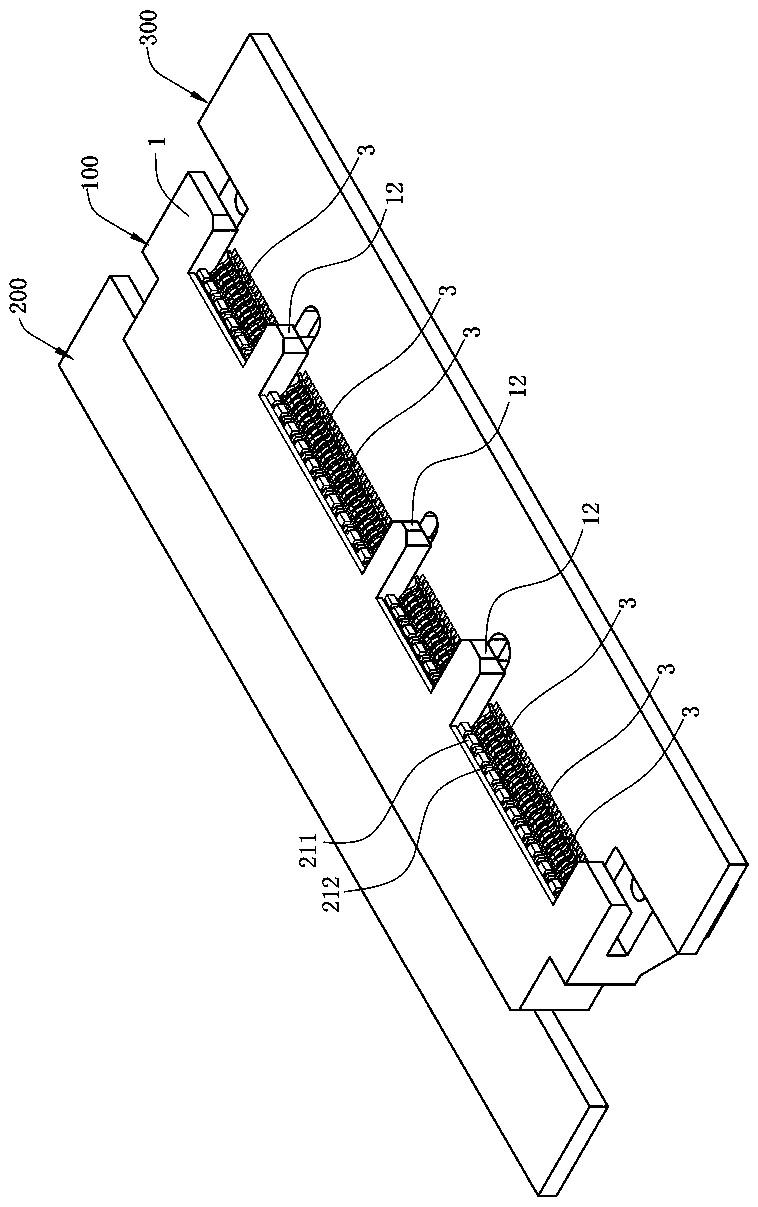
[0027] see figure 1 , figure 2 and image 3 , which is an embodiment of the present invention, an electrical connector 100 for electrically connecting an electronic card 200 and a circuit board 300, comprising an insulating housing 1 and a plurality of terminal modules 2 arranged in two rows up and down. In the insulating housing 1 , the terminal module 2 includes an insulating block 2A and a plurality of terminals 3 embedded with the insulating block 2A. The terminals 3 of the upper row of terminal modules 2 and the terminals 3 of the lower row of terminal modules 2 are symmetrically arranged by turning 180° along the vertical direction and clamp the electronic card 200 up and down together.

[0028] see figure 1 , Figu...


PUM


Abstract

The invention discloses an electric connector which is used for being inserted and connected into a butt joint element forwardly. The electric connector is characterized by comprising an insulating block, a plurality of pairs of differential signal terminals and a plurality of grounding terminals, wherein a plurality of first protruding blocks and a plurality of second protruding blocks are arranged on the front surface of the insulating block in a protruding mode; the first protruding block and the second protruding block are adjacently arranged, and a groove is formed between every two adjacent first protruding blocks and the second protruding blocks; the plurality of pairs of differential signal terminals and the plurality of grounding terminals are embedded in the insulating blocks; each differential signal terminal is embedded in the corresponding first protruding block and extends out of the first protruding block, and is used for electrically contacting the butt joint element; afirst side surface is arranged on each of the left side and the right side of the pair of differential signal terminals separately; the grounding terminals are arranged between the two adjacent pairsof differential signal terminals; each grounding terminal is embedded in the corresponding second protruding block and extends out of the second protruding block, and is used for electrically contacting the butt joint element; a second side surface is arranged on each of the left side and the right side of the grounding terminal separately; and the medium between the first side surface and the second side surface is air.

Description

technical field [0001] The invention relates to an electrical connector, in particular to an electrical connector for transmitting high-speed signals. Background technique [0002] With the public's requirements for high transmission rates of electronic products, most of the current electrical connectors must consider the high frequency requirements. A known electrical connector is used to realize the electrical connection between an electronic card and a circuit board to realize signal transmission. The electrical connector has an insulating shell, a slot at the front end for accommodating an electronic card, and a mounting groove at the rear end for accommodating the terminal module. The terminal module has a plurality of terminals and an insulating block injection-molded with the terminals. The plurality of terminals include a plurality of pairs of differential signal terminals for transmitting high-frequency signals and a plurality of ground terminals located between tw...

Claims


Application Information

Patent Timeline
Patent Type & Authority Applications(China)
IPC IPC(8): H01R12/72H01R12/73H01R13/40H01R13/46H01R13/6461H01R13/6464H01R13/6477H01R31/06
CPCH01R12/721H01R12/732H01R13/40H01R13/46H01R13/6461H01R13/6464H01R13/6477H01R31/06H01R12/714H01R13/405H01R13/6471
Inventor 冯志军王康
Owner DEYI PRECISION ELECTRONIC IND CO LTD PANYU
Why Eureka
Try Eureka