
Tone regulation and control circuit based on NE5532 chip

A technology for regulating circuits and tone control, applied in transducer circuits, electrical components, sensors, etc., can solve the problems of fuzzy bass, sharp treble, no need to mention subwoofer, etc., to simplify the circuit structure, eliminate interference, The effect of reducing product cost

Inactive Publication Date: 2018-11-16
SHENZHEN INST OF ADVANCED TECH
View PDF5 Cites 7 Cited by
  • Summary
  • Abstract
  • Description
  • Claims
  • Application Information

AI Technical Summary

Problems solved by technology

Commercially available tone boards include finished speakers, most of which are sharp and piercing, especially the bass is fuzzy, not to mention the subwoofer, which cannot meet the requirements of ordinary home audio
In addition, most of the audio equipment on the market today needs tone boards to compensate for the fact that the preamplifiers and power amplifiers are not of the highest quality. However, most of the tone boards on the market, including finished audio, are sharp and piercing, and the bass is fuzzy, especially The subwoofer effect is poor and cannot meet the needs of consumers
[0003] Existing audio signal conditioning circuits usually use multiple amplifiers and multiple filters, including a circulator, a switch limiter, a first power amplifier, an attenuator, a transceiver switch, a third power amplifier, a second filter, and a limiter , the second power amplifier, etc., which not only ensure the signal-to-noise ratio of the signal, but also ensure the gain of the signal, and provide a certain amount of power for subsequent signal analysis or signal transmission, but such circuits still have complex circuit structures and high costs. , poor sound quality and other issues, unable to meet user needs

Method used


Image

  • Tone regulation and control circuit based on NE5532 chip
  • Tone regulation and control circuit based on NE5532 chip
  • Tone regulation and control circuit based on NE5532 chip

Examples


Embodiment Construction

[0022] The present invention will be described in more detail below in conjunction with the accompanying drawings and embodiments.

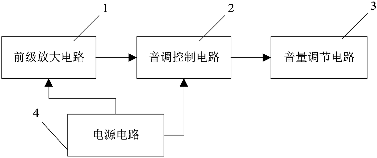
[0023] The invention discloses a tone control circuit based on the NE5532 chip, combining Figure 1 to Figure 5 As shown, it includes:

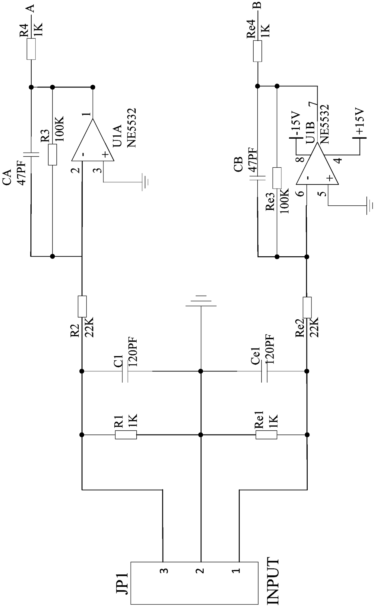
[0024] A preamplifier circuit 1, its two input terminals are respectively used to access the left channel audio signal and the right channel audio signal, the preamplifier circuit 1 includes amplifier U1A and amplifier U1B, the amplifier U1A and amplifier U1B Integrated in a NE5532 chip, the amplifier U1A and the amplifier U1B are respectively used to amplify the left channel audio signal and the right channel audio signal;

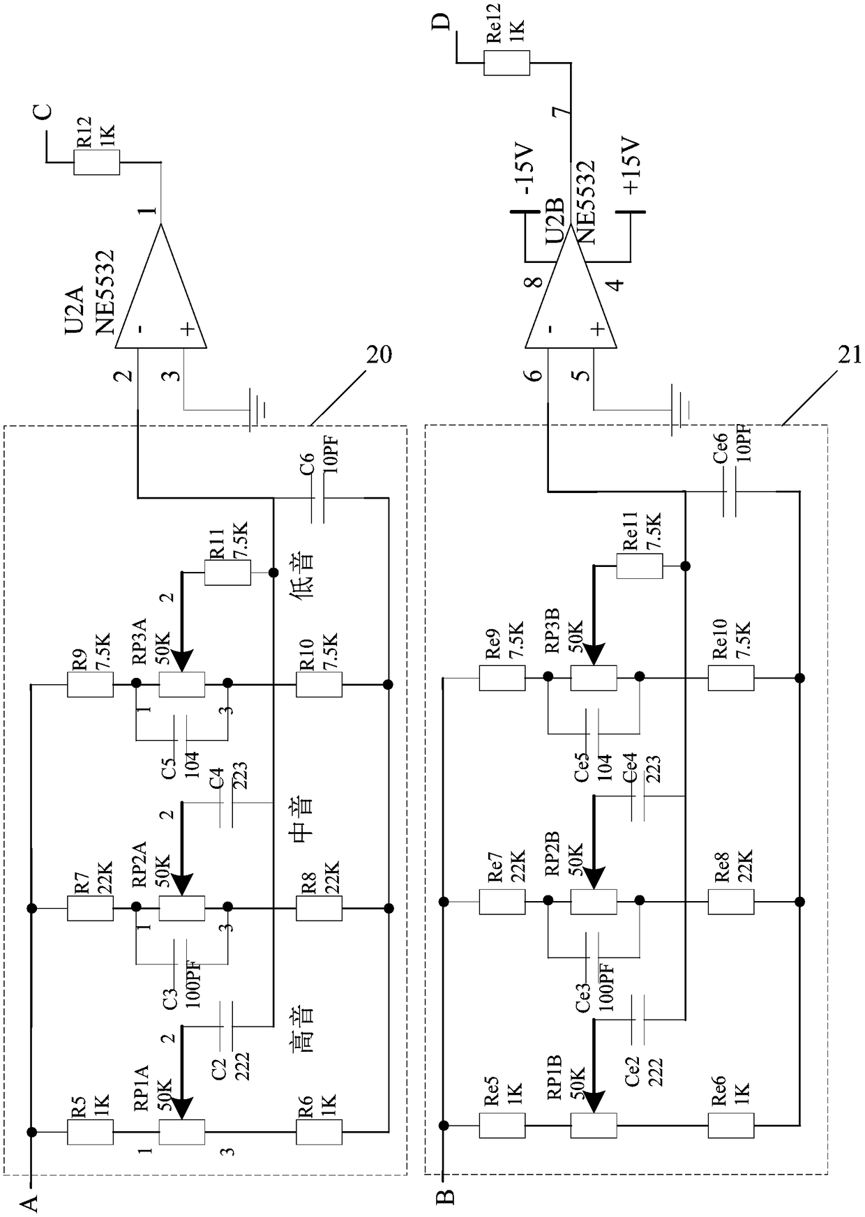
[0025] A tone control circuit 2, the two input ends of which are respectively connected to the output ends of the amplifier U1A and the amplifier U1B, and the tone control circuit 2 is used to adjust the bass, middle tone and the middle tone of the two audio signals amplified by the amplif...


PUM


Abstract

The invention discloses a tone regulation and control circuit based on a NE5532 chip; the tone regulation and control circuit comprises the following parts: a pre-stage amplification circuit with twoinput ends respectively connected with a left channel audio signal and a right channel audio signal, the pre-stage amplification circuit comprises an amplifier U1A and an amplifier U1B, the amplifierU1A and the amplifier U1B are integrated in the NE5532chip, and respectively are used for amplifying the left channel audio signals and the R channel audio signals; a tone control circuit with two input ends respectively connected with output ends of the amplifier U1A and the amplifier U1B, the tone control circuit is used for respectively adjusting low pitch, middle pitch and high pitch for the two paths of audio signals amplified by the amplifier U1A and the amplifier U1B; a volume adjusting circuit used for adjusting volumes of the two paths of audio signals. The tone regulation and controlcircuit can better amplify, rectify and filter sounds and make fidelity treatment, and can remove unnecessary interferences, thus further obtaining better sound quality.

Description

technical field [0001] The invention relates to an audio signal adjustment circuit, in particular to a tone adjustment circuit based on the NE5532 chip. Background technique [0002] Due to the limited space in modern family rooms, audio miniaturization is also a development direction of consumer audio products, and the timbre of small and medium speakers is prone to problems such as thin and delicate. Commercially available tone boards include finished speakers, most of which are sharp and harsh, especially the bass is blurred, not to mention the subwoofer, which cannot meet the requirements of ordinary home audio. In addition, most of the audio equipment on the market today needs tone boards to compensate for the fact that the preamplifiers and power amplifiers are not of the highest quality. However, most of the tone boards on the market, including finished audio, are sharp and piercing, and the bass is fuzzy, especially The subwoofer effect is poor and cannot meet the n...

Claims


Application Information

Patent Timeline
Patent Type & Authority Applications(China)
IPC IPC(8): H04R3/00
CPCH04R3/00H04R2430/00
Inventor 杜文静王磊王荦荦李慧慧
Owner SHENZHEN INST OF ADVANCED TECH
Learn More