Airborne spray cooling system for cooling circulating water by using ram air and evaporative refrigeration cycle

A technology of ram air and circulating cooling, which is applied in the direction of cooling/ventilation/heating transformation, electrical components, electrical equipment structural parts, etc., and can solve problems such as being unable to be put into use at any time, difficult to install military aircraft, and long storage time

Pending Publication Date: 2018-11-16
NANJING UNIV OF TECH
View PDF8 Cites 7 Cited by
  • Summary
  • Abstract
  • Description
  • Claims
  • Application Information

AI Technical Summary

Problems solved by technology

[0005] Some patents have proposed the application method of spray cooling in the airborne field. For example, patent ZL201510072716.7 proposes a cooling system based on air expansion refrigeration for airborne heating elements. The main feature is the use of turbines as refrigeration devices and power sources. When this solution is put into use, the turbine cooling storage must be used first for spray cooling, and the cooling storage time is long, so it cannot be put into use at any time; the structure is complex and the equipment space is large, and it is difficult to install on military aircraft
Patent ZL201510072716.7 proposes a cooling system for onboard heating elements based on air expansion refrigeration. The main feature is that the turbine is used as the cooling device and power source. In this solution, the cooling source is completely provided by the turbine, which increases the original turbine refrigeration of the aircraft. The load of the system is not good for the long-term stable operation of the aircraft

Method used


Image

  • Airborne spray cooling system for cooling circulating water by using ram air and evaporative refrigeration cycle
  • Airborne spray cooling system for cooling circulating water by using ram air and evaporative refrigeration cycle
  • Airborne spray cooling system for cooling circulating water by using ram air and evaporative refrigeration cycle

Examples


Embodiment Construction

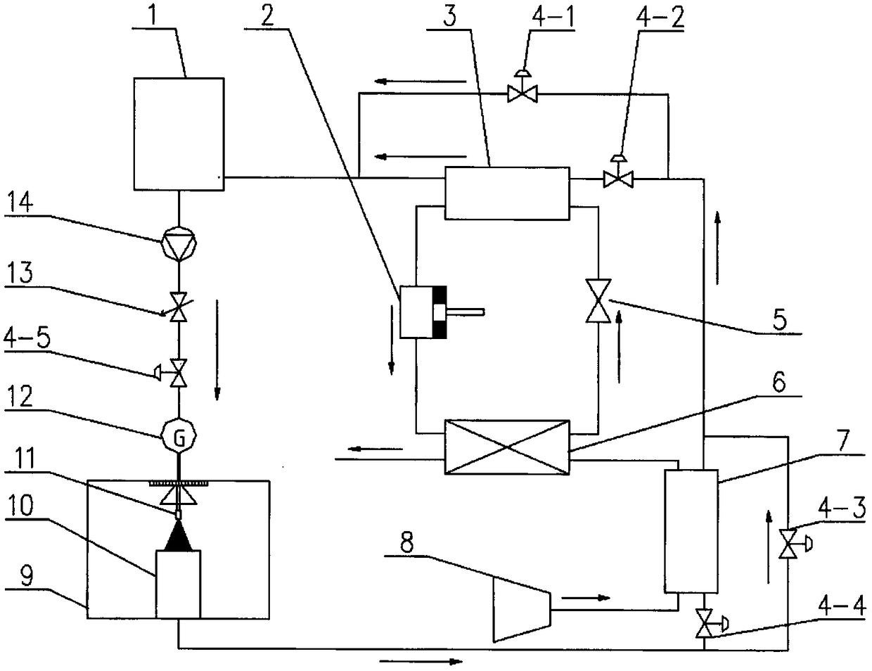
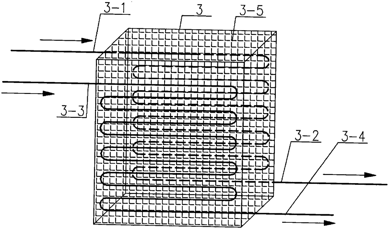
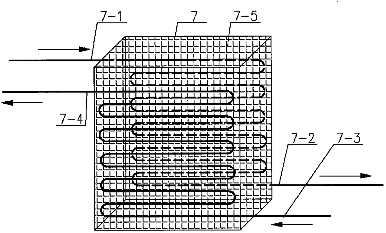
[0030] Such as figure 1 As shown, an airborne spray cooling system using ram air and evaporative refrigeration cycle cooling circulating water mainly includes a water tank 1, a compressor 2, an evaporator 3, a cold water inlet 3-1, a cold water outlet 3-2, and a refrigerant inlet 3 -3. Refrigerant outlet 3-4, phase change material 3-5, first stop valve 4-1, second stop valve 4-2, third stop valve 4-3, fourth stop valve 4-4, Five stop valves 4-5, expansion valves 5, condensers 6, phase change material heat exchangers 7, cold air inlets 7-1, cold air outlets 7-2, cold water inlets 7-3, cold water outlets 7-4, phase change materials 7-5. Ram air inlet 8, spray chamber 9, surface to be cooled 10, nozzle 11, flow meter 12, flow regulating valve 13, water pump 14.

[0031] Before the aircraft takes off, the running time of the spray cooling system is obtained according to the flight time of the aircraft and the required cooling time of the equipment, and a certain amount of water is ...


PUM


Abstract

The invention discloses an airborne spray cooling system for cooling circulating water by using ram air and an evaporative refrigeration cycle, and belongs to the cooling field of airborne high-heat-flux-density equipment. The system is mainly used for solving the continuous heat dissipation of high-heat-flux-density surfaces such as an airborne radar chip and a laser weapon and mainly includes awater tank, a compressor, an evaporator, a cold water inlet, a cold water outlet, a refrigerant inlet, a refrigerant outlet, a phase change material, an expansion valve, a condenser, a phase change material heat exchanger, a ram air inlet, a spray chamber, a to-be-cooled surface, a nozzle, a flow meter, a flow control valve and a water pump. The system, by using the latent heat of vaporization ofwater, cools the surface of a high-temperature electronic device in the spray chamber, uses the ram air as a main cold source, uses an evaporative refrigeration cycle as an auxiliary cold source, usestwo phase change materials as an intermediate energy storage medium to correspond to the two cold sources, and selects a cold source combination mode according to the surface temperature. The systemis safe, stable, and energy-efficient in operation, and meets the cooling needs in airborne complex environments.

Description

Technical field [0001] The invention relates to an airborne spray cooling system using stamping air and evaporative refrigeration cycle to cool circulating water, belonging to the field of airborne high heat flux electronic equipment cooling. Background technique [0002] With the rapid development of airborne radar technology, power amplifier chips have developed from silicon chips and GaAs chips to the third-generation semiconductor GaN chips. Several projects of the U.S. Navy and Air Force have shown that the heat flux density of GaN chips under research has reached 500W / cm 2 , the heat flux density of future chips will exceed 1000W / cm 2 . At the same time, with the continuous improvement of military aircraft maneuverability, stealth performance, and defense performance requirements, technologies such as high-power laser technology, high integration and miniaturization of electronic components have been developed rapidly. Laser weapons will generate megawatt-level heat...

Claims


Application Information

Patent Timeline
Patent Type & Authority Applications(China)
IPC IPC(8): H05K7/20H01L23/427H01L23/467H01L23/473
CPCH05K7/20345H01L23/427H01L23/467H01L23/473
Inventor 王瑜邱兰兰刘金祥牛晓峰
Owner NANJING UNIV OF TECH
Why Eureka
Try Eureka