Method and device for ultrasonic imaging as well as ultrasonic imaging equipment

An ultrasonic imaging method and ultrasonic imaging technology are applied in the directions of ultrasonic/sonic/infrasonic diagnosis, ultrasonic/sonic/infrasonic image/data processing, and acoustic diagnosis, which can solve the problems of poor imaging contrast and low resolution, and achieve improved Contrast, good image resolution, the effect of increasing image resolution

Inactive Publication Date: 2018-11-20
NEUSOFT MEDICAL SYST CO LTD
View PDF6 Cites 13 Cited by
  • Summary
  • Abstract
  • Description
  • Claims
  • Application Information

AI Technical Summary

Problems solved by technology

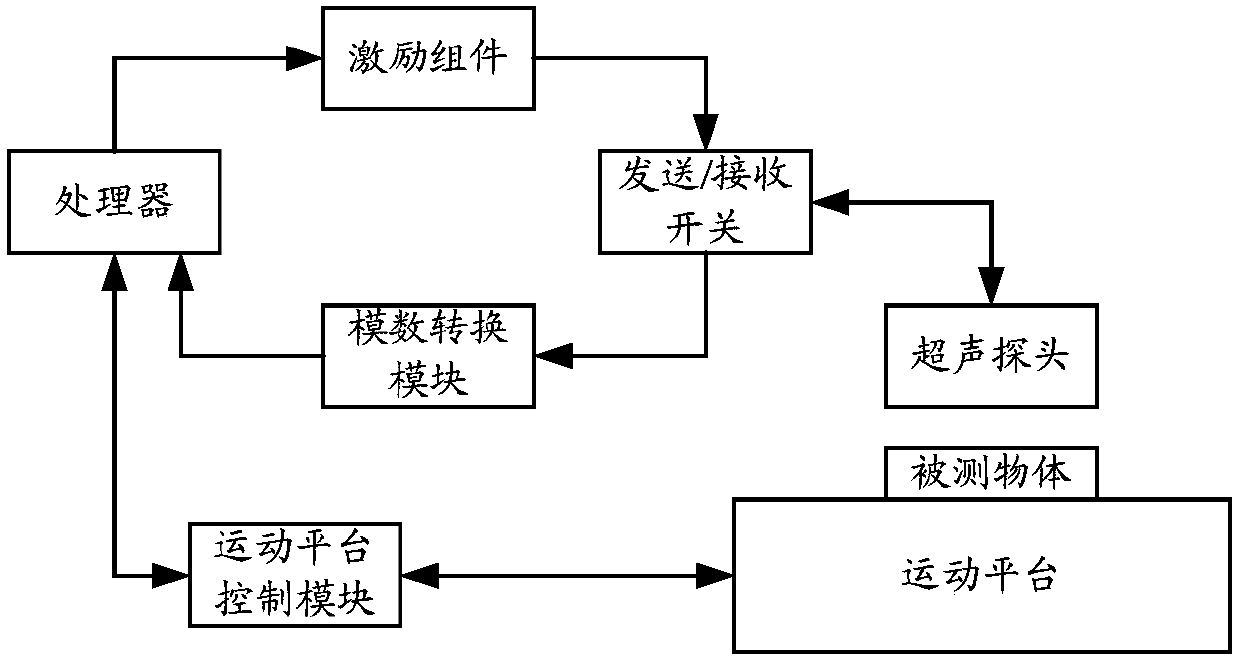
[0005] In view of this, the present application provides an ultrasonic imaging method, device and ultrasonic imaging equipment to solve the problems of low resolution and poor imaging contrast of ultrasonic images obtained by existing methods

Method used


Image

  • Method and device for ultrasonic imaging as well as ultrasonic imaging equipment
  • Method and device for ultrasonic imaging as well as ultrasonic imaging equipment
  • Method and device for ultrasonic imaging as well as ultrasonic imaging equipment

Examples


Embodiment Construction

[0029] Reference will now be made in detail to the exemplary embodiments, examples of which are illustrated in the accompanying drawings. When the following description refers to the accompanying drawings, the same numerals in different drawings refer to the same or similar elements unless otherwise indicated. The implementations described in the following exemplary embodiments do not represent all implementations consistent with this application. Rather, they are merely examples of apparatuses and methods consistent with aspects of the present application as recited in the appended claims.

[0030] The terminology used in this application is for the purpose of describing particular embodiments only, and is not intended to limit the application. As used in this application and the appended claims, the singular forms "a", "the", and "the" are intended to include the plural forms as well, unless the context clearly dictates otherwise. It should also be understood that the term...


PUM


Abstract

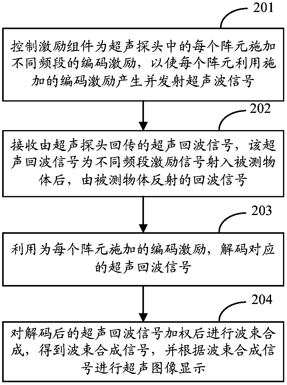
The application provides a method and a device for ultrasonic imaging as well as ultrasonic imaging equipment. The method comprises the following steps: a control excitation component applies coded excitation of different frequencies to each array element in an ultrasonic probe, so as to enable each array element to utilize the applied coded excitation for producing and emitting ultrasonic signals; ultrasonic echo signals returned by the ultrasonic probe are received; the coded excitation applied to each array element is utilized for decoding the corresponding ultrasonic echo signals; and beam forming is carried out after the decoded ultrasonic echo signals are weighted, so as to obtain beam forming signals and display ultrasonic images according to the beam forming signals. Through the way of applying the coded excitation of different frequencies to each array element, the invention can increase the energy carried by the ultrasonic signals, promote the penetration force, enable the received ultrasonic echo signals not to interfere with each other and improve the image contrast. The image resolution is also improved by adopting the weighting method for beam forming.

Description

technical field [0001] The present application relates to the technical field of medical equipment, in particular to an ultrasound imaging method, device and ultrasound imaging equipment. Background technique [0002] In medical ultrasound imaging, beamforming is one of the core processing steps of ultrasound imaging. Usually, the ultrasonic probe in the ultrasonic imaging equipment sends ultrasonic signals through multiple array elements into the object under test, and then receives the ultrasonic echo signals reflected by the object under test through each array element, and transmits them back to the ultrasonic imaging equipment In the processor, the processor performs beamforming on the ultrasonic echo signals returned by each array element to obtain the beamforming signal, and performs ultrasonic image display according to the beamforming signal. [0003] In related technologies, the beamforming process usually adopts DAS (Delay And Sum, delay superposition) method and...

Claims


Application Information

Patent Timeline
Patent Type & Authority Applications(China)
IPC IPC(8): A61B8/00
CPCA61B8/52A61B8/5207
Inventor 金晶王博
Owner NEUSOFT MEDICAL SYST CO LTD
Why Eureka
Try Eureka