
Non-standard tool facilitating workpiece movement

A workpiece movement, non-standard technology, applied in the direction of conveyor objects, transportation and packaging, etc., can solve the problems that the equipment cannot be realized at the same time, fall to the ground, and the removal of the workpiece is not convenient and simple, so as to facilitate the removal of the workpiece and prevent Shake at will, improve the effect of safety

Active Publication Date: 2018-11-20
合肥鹏锦智能装备有限公司
View PDF4 Cites 0 Cited by
  • Summary
  • Abstract
  • Description
  • Claims
  • Application Information

AI Technical Summary

Problems solved by technology

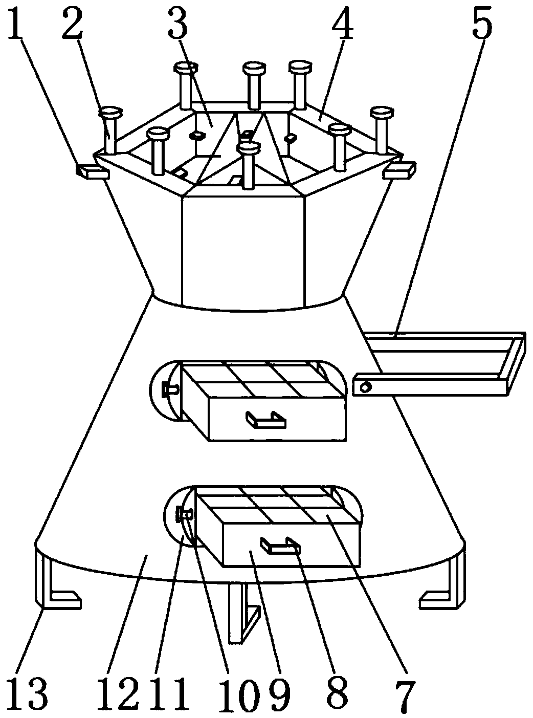
[0002] A workpiece requires a variety of machines to process it. In the process of processing, since various processing machines are located in different positions, the workpiece needs to be moved in multiple places during the process of processing. In mechanical production, conveyor chains or conveyor belts are often used to transfer products. , but the conveyor chain or conveyor belt can only move the workpiece on the assembly line. When transporting the workpiece to a machine that is not on the assembly line for processing, it is often necessary to carry the workpiece manually. In order to reduce the labor intensity of the workers, we have invented a non-standard workpiece that is convenient for the workpiece to move The workpiece cannot be fixed on the existing carrying equipment, and may fall to the ground due to bumps during transportation; the workpiece is not convenient and simple when it is taken off; Stability during placement

Method used


Image

  • Non-standard tool facilitating workpiece movement
  • Non-standard tool facilitating workpiece movement
  • Non-standard tool facilitating workpiece movement

Examples


Embodiment Construction

[0030] The following will clearly and completely describe the technical solutions in the embodiments of the present invention with reference to the accompanying drawings in the embodiments of the present invention. Obviously, the described embodiments are only some, not all, embodiments of the present invention. Based on the embodiments of the present invention, all other embodiments obtained by persons of ordinary skill in the art without making creative efforts belong to the protection scope of the present invention.

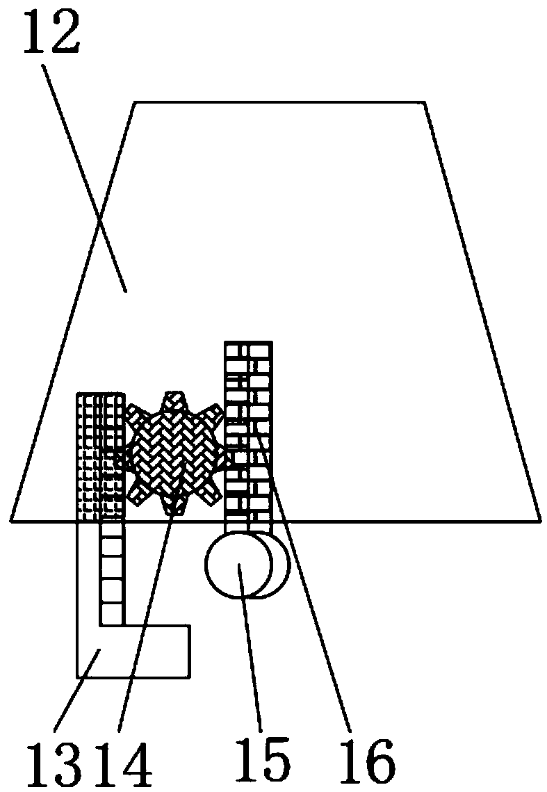
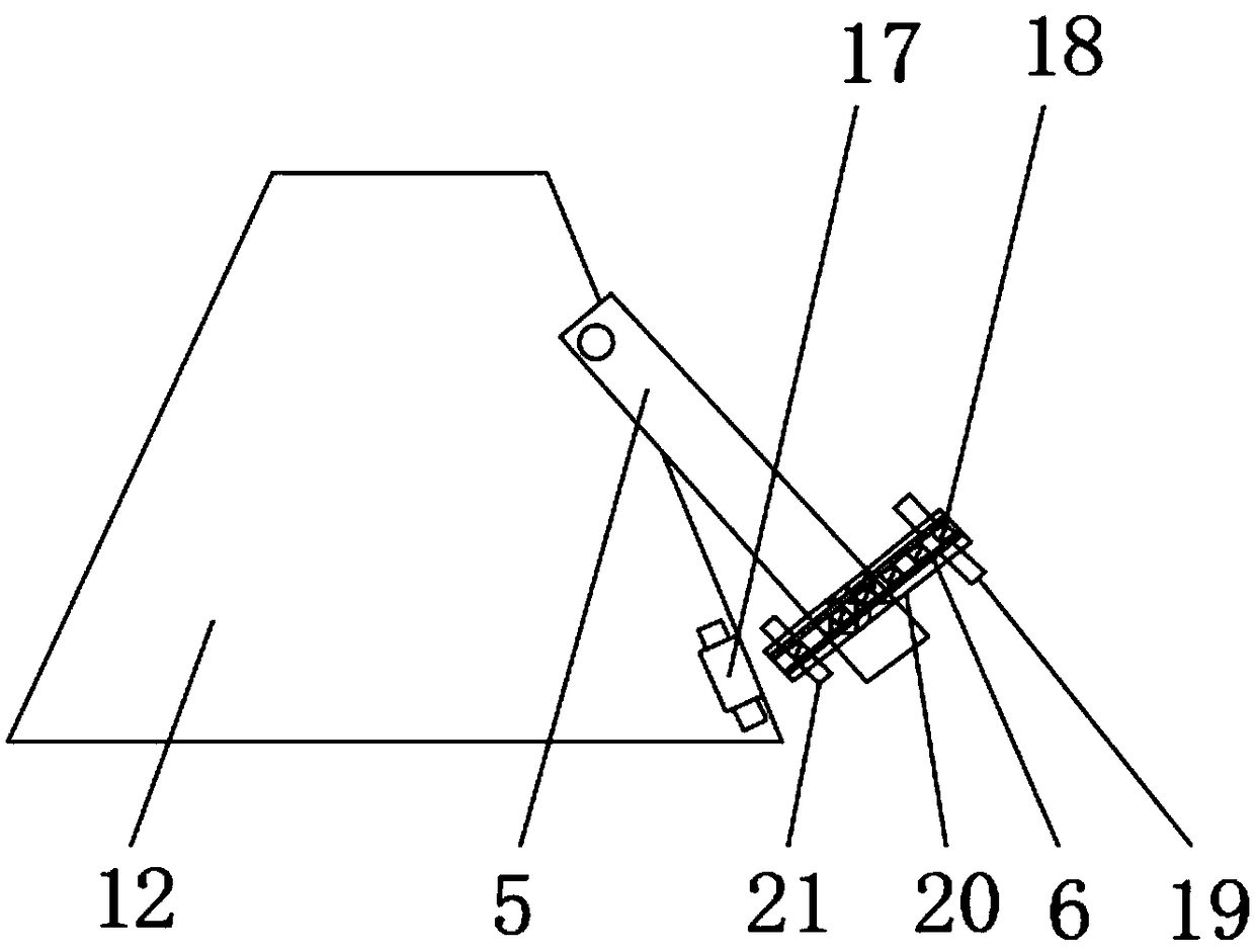
[0031] see Figure 1-6, the present invention provides a technical solution: a non-standard tooling that facilitates the movement of workpieces, including a main body 12, a first placement box 4 is fixedly installed on the outer surface of the upper end of the main body 12, and the first placement box 4 can hold some larger The workpiece, and the outer surface of the upper end of the first placement box 4 is fixedly installed with a connecting bolt 2, the oute...


PUM


Abstract

The invention discloses a non-standard tool facilitating workpiece movement. The non-standard tool comprises a main body, wherein the outer surface of the upper end of the main body is fixedly provided with a first placing box, and connecting bolts are fixedly installed on the outer surface of the upper end of the first placing box; rotating discs are fixedly installed on the outer surfaces of theupper ends of the connecting bolts, and second control gears are fixedly installed on the outer surfaces of the lower ends of the connecting bolts; second wheel teeth are fixedly installed on the outer surfaces of one sides of the second control gears, and limiting columns are arranged on one sides of the second wheel teeth; and second tooth grooves are formed in the outer surfaces of one sides of the limiting columns, and first placing grooves are formed in one sides of the connecting bolts. According to the non-standard tool facilitating workpiece movement, a workpiece can be prevented frombeing damaged by collision in the moving process, the operation is more convenient and labor-saving when the workpiece is taken down, so that equipment is quickly and flexibly moved when moved, and the equipment can be stably placed at a fixed position when placed.

Description

technical field [0001] The invention relates to the field of easy movement of workpieces, in particular to a non-standard tooling for facilitating the movement of workpieces. Background technique [0002] A workpiece requires a variety of machines to process it. In the process of processing, since various processing machines are located in different positions, the workpiece needs to be moved in multiple places during the process of processing. In mechanical production, conveyor chains or conveyor belts are often used to transfer products. , but the conveyor chain or conveyor belt can only move the workpiece on the assembly line. When transporting the workpiece to a machine that is not on the assembly line for processing, it is often necessary to carry the workpiece manually. In order to reduce the labor intensity of the workers, we have invented a non-standard workpiece that is convenient for the workpiece to move The workpiece cannot be fixed on the existing carrying equipm...

Claims


Application Information

Patent Timeline
IPC IPC(8): B65G47/74
CPCB65G47/74
Inventor 谢伟鹏朱啊楠
Owner 合肥鹏锦智能装备有限公司
Learn More