
Wire unwinding device for electric construction

A technology of pay-off device and electric construction, which is applied in the directions of transportation and packaging, transportation of filamentous materials, and processing of thin materials, etc., can solve the problems of low tensile strength, breakage and damage of power wires, etc. Reduce the effect of disconnection

Inactive Publication Date: 2018-11-20
张秋达
View PDF0 Cites 3 Cited by
  • Summary
  • Abstract
  • Description
  • Claims
  • Application Information

AI Technical Summary

Problems solved by technology

[0002] The pay-off device is divided into ground cable pulley, cable pulley, sky pulley, nylon pulley, cable wire pay-off pulley, large-diameter pay-off pulley, double-purpose pay-off pulley for hanging, ground wire pay-off pulley, and lifting pulley. It plays a protective role when laying cable conductors, saving time and effort. The use of ground cable pulleys is used for cable extension and changing directions to protect cables from friction. It is a kind of pay-off device for electric power construction in the current technology. The pay-off device still relies on the guide wheel or by gravity or tension to pay off the wire. There is not much problem of wire breakage when used on wires with thick wire diameter or high tension resistance. However, with the progress of ultra-thin wire , the tensile strength of the ultra-fine wire itself is very small, and the pay-off device meets the requirements for unwinding the ultra-thin wire. If the same method is used to pay off the wire, the power wire will be broken and damaged.

Method used


Image

  • Wire unwinding device for electric construction
  • Wire unwinding device for electric construction
  • Wire unwinding device for electric construction

Examples


Embodiment Construction

[0022] In order to make the technical means, creative features, goals and effects achieved by the present invention easy to understand, the present invention will be further described below in conjunction with specific embodiments.

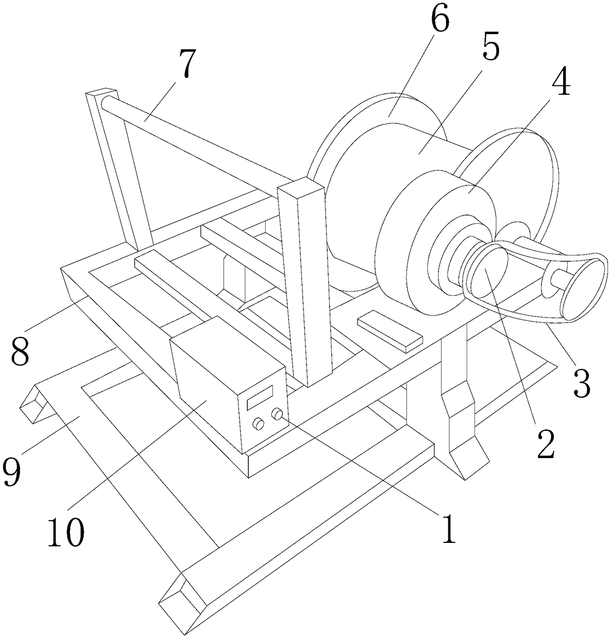
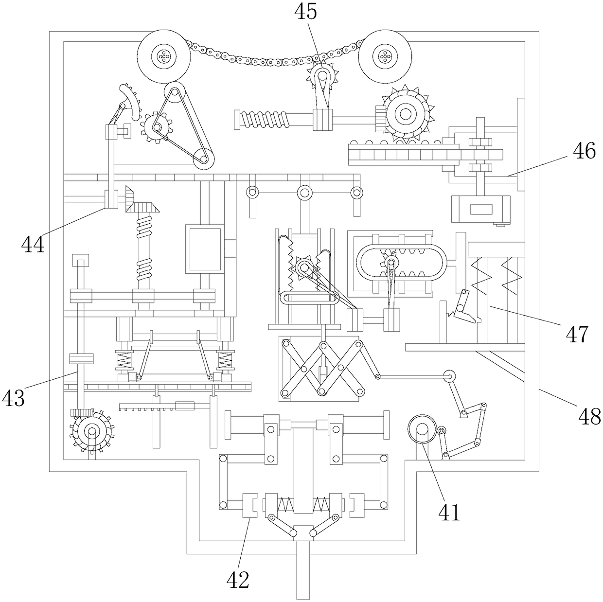
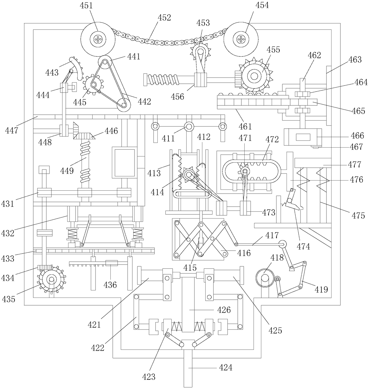
[0023] see Figure 1-Figure 4, the present invention provides a pay-off device for electric power construction: its structure includes a mode adjustment button 1, a hub 2, a mechanical chain 3, a damper device 4, a pay-off disc 5, a limit plate 6, a connecting rod 7, and a metal bracket 8. Base 9, controller 10, the mode adjustment button 1 is provided with two and respectively inlaid in the center of the surface of the controller 10, the controller 10 is fixed on the top of the metal bracket 8 by screws, and the metal bracket 8 Be fixed on the top of the base 9 by screw rods, the connecting rod 7 is welded on the top of the metal bracket 8, the limit plate 6 is provided with two and fixed on the right side of the metal bracket 8 by screw rods res...


PUM


Abstract

The invention discloses a wire unwinding device for electric construction. The device comprises a mode adjusting button, a hub, a mechanical chain, a damper device, a wire unwinding disc, a limiting plate, a connecting rod, a metal bracket, a base and a controller; and the damper device is provided with a linkage trigger device, an ascending adjusting device, a turbine driving device, a transmission device, a friction speed reducing device, a movable adjusting device, a trigger startup device and a metal edge frame. The device has the following beneficial effects: the motion resistance can beprovided through the added damper device; and the wire unwinding tension is preferably controlled through a motion energy reducing device, and the wire unwinding tension of leads is always stabilizedat a critical value between deformation and no deformation, so that ultrafine leads are preferably protected, wires can be arranged at a wiring end more stably, the conditions of wire breakage and flight are reduced, the long-time ordered construction work is facilitated, and the construction period is shortened.

Description

technical field [0001] The invention is a pay-off device for electric power construction, which belongs to the field of pay-off devices. Background technique [0002] The pay-off device is divided into ground cable pulley, cable pulley, sky pulley, nylon pulley, cable wire pay-off pulley, large-diameter pay-off pulley, double-purpose pay-off pulley for hanging, ground wire pay-off pulley, and lifting pulley. It plays a protective role when laying cable conductors, saving time and effort. The use of ground cable pulleys is used for cable extension and changing directions to protect cables from friction. It is a kind of pay-off device for electric power construction in the current technology. The pay-off device still relies on the guide wheel or by gravity or tension to pay off the wire. There is not much problem of wire breakage when used on wires with thick wire diameter or high tension resistance. However, with the progress of ultra-thin wire , the tensile strength of the ...

Claims


Application Information

Patent Timeline
IPC IPC(8): B65H49/20B65H49/32B65H59/38
CPCB65H49/20B65H49/32B65H59/387B65H2701/34
Inventor 张秋达
Owner 张秋达
Learn More