Small-scale copper wire winding mechanism with automatic shearing device

A technology of shearing device and winding mechanism, which is used in transportation and packaging, transportation of filamentous materials, and thin material processing, etc., can solve the problems of low efficiency, long stop time, manual unloading, etc., and achieve high efficiency and improve The effect of production efficiency and short replacement time

Inactive Publication Date: 2018-11-20
FOSHAN XUNAOJIE AUTOMATION TECH CO LTD
View PDF5 Cites 6 Cited by
  • Summary
  • Abstract
  • Description
  • Claims
  • Application Information

AI Technical Summary

Problems solved by technology

[0002] The existing thin copper wire is generally wound by a small cylinder, and generally only one small cylinder can be installed in the winding mechanism for winding. After one is completed, it needs to be unloaded manually, which is very troublesome, especially for In continuous production, the stop time in the middle is long and the efficiency is low; and in the replacement, it needs to cut off the connection end of the coiled small cylinder with scissors to remove it, which is very troublesome

Method used


Image

  • Small-scale copper wire winding mechanism with automatic shearing device
  • Small-scale copper wire winding mechanism with automatic shearing device
  • Small-scale copper wire winding mechanism with automatic shearing device

Examples


Embodiment

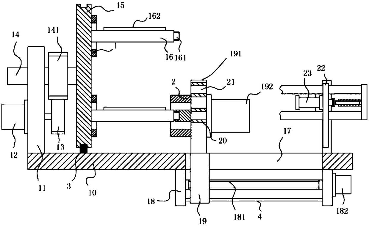
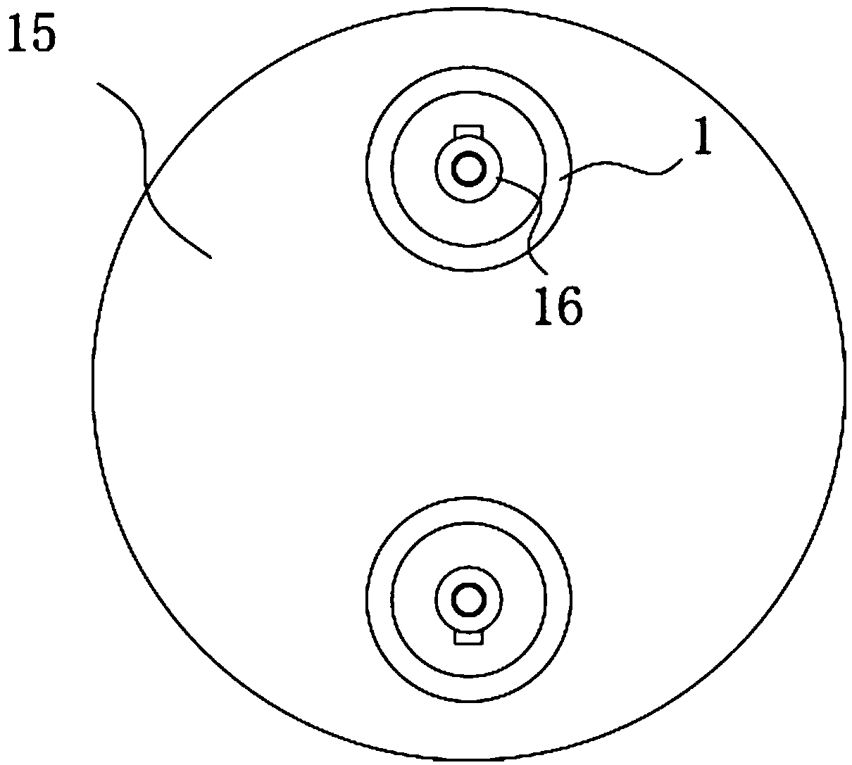
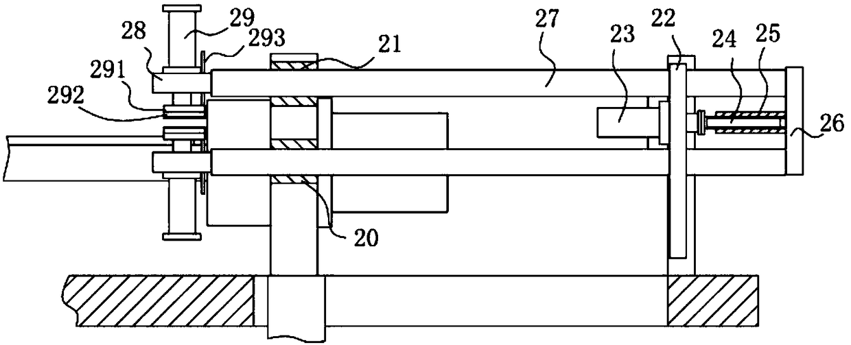
[0021] Example: see Figure 1 to Figure 3 As shown, a small-sized copper wire winding mechanism with an automatic shearing device includes a main base plate 10, a vertical support plate 11 is fixed on the left top surface of the main base plate 10, and the left side wall of the vertical support plate 11 Servomotor 12 is fixed on it, the output shaft of servomotor 12 passes through vertical support plate 11 and is fixed with driving gear 13, the top of vertical support plate 11 is hinged with rotating main shaft 14 through bearing, and the right part of rotating main shaft 14 protrudes Vertical support plate 11 is fixed with transmission gear 141, and transmission gear 141 is meshed with rotation gear 13, and the right end of rotation main shaft 14 is fixed with main circular rotary plate 15, and the top and bottom of the right side wall of main circular rotary plate 15 Both are hinged with a transverse shaft 16 through bearings, and the right end of the transverse shaft 16 is ...


PUM


Abstract

The invention discloses a small-scale copper wire winding mechanism with an automatic shearing device. The small-scale copper wire winding mechanism comprises a main base plate, a moving straight slotis formed in the right bottom surface of the main base plate, and lower supporting plates are fixed to the bottom surface of the main base plate of the left and right sides of the moving straight slot. Two ends of a horizontal screw rod are hinged to the two lower supporting plates through bearings, wherein a moving motor is fixed to the outside wall of one of the two lower supporting plates. A moving block is connected to the horizontal screw rod in a threaded mode, and the upper portion of the moving block is sleeved with the moving straight slot in an inserted mode. A locating plate is fixed to the top surface of the moving block and located above the main base plate, two guide blocks are fixed to the front wall surface of the locating plate, and horizontal guide through holes are formed in the guide blocks. Two small barrel bodies can be mounted, a small barrel body can automatically shear off a winding connecting end after finished, the finished small barrel body is located abovethrough a main circular rotating plate rotating, the small barrel body to be finished is located below and automatically fixes to process, the efficiency is high, the replacement time of the middle part is short, and the efficiency is high.

Description

technical field [0001] The invention relates to the technical field of metal wire processing equipment, in particular to a small copper wire winding mechanism with an automatic shearing device. Background technique [0002] The existing thin copper wire is generally wound by a small cylinder, and generally only one small cylinder can be installed in the winding mechanism for winding. After one is completed, it needs to be unloaded manually, which is very troublesome, especially for In continuous production, the stop time in the middle part is long, and the efficiency is low; and in the replacement, it needs to cut off the connection end of the wound small cylinder with scissors to remove it, which is very troublesome. Contents of the invention [0003] The purpose of this invention is to address the deficiencies of the prior art, and to provide a small copper wire winding mechanism with an automatic shearing device, which can be installed with two small cylinders, and afte...

Claims


Application Information

Patent Timeline
Patent Type & Authority Applications(China)
IPC IPC(8): B65H67/08B65H67/052B65H54/553
CPCB65H67/081B65H54/553B65H67/052B65H2701/36
Inventor 叶小桥
Owner FOSHAN XUNAOJIE AUTOMATION TECH CO LTD
Why Eureka
Try Eureka