
Heat radiating device of inner wall of wind turbine generator system

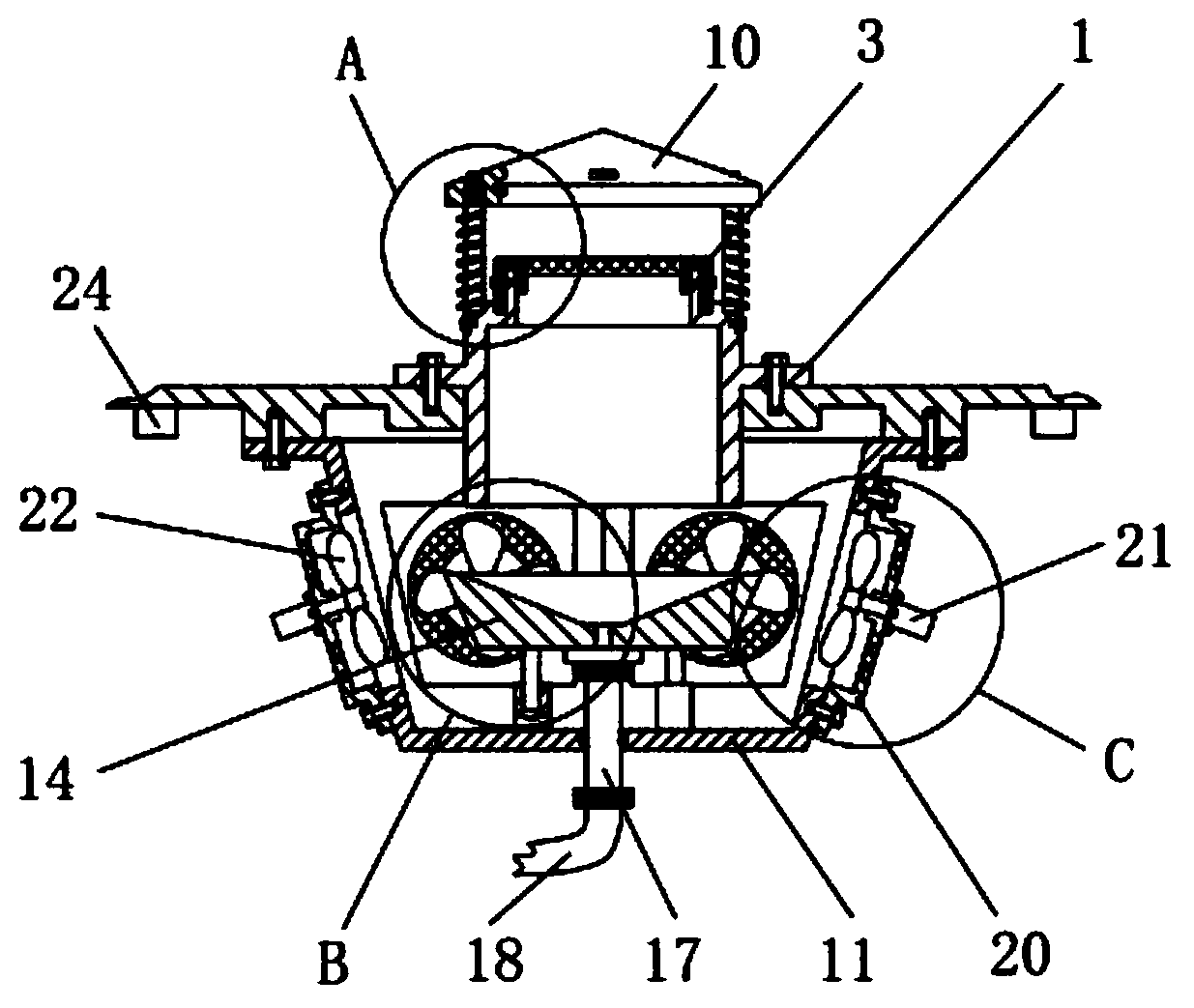
A technology for wind turbines and cooling devices, which is applied to wind turbines, installation/support configuration of wind turbines, monitoring of wind turbines, etc. It can solve the problem of rising temperature of wind turbines, low heat dissipation efficiency of radiators, and affecting normal operation of equipment and other issues, to achieve the effect of easy disassembly, enhanced heat dissipation, and avoid damage

Active Publication Date: 2018-11-20
十堰善新新能源科技有限公司
View PDF7 Cites 3 Cited by
  • Summary
  • Abstract
  • Description
  • Claims
  • Application Information

AI Technical Summary

Problems solved by technology

[0002] A lot of equipment in the wind turbine will emit a lot of heat after running for a certain period of time, which will increase the temperature inside the tower of the wind turbine and affect the normal operation of the equipment
The heat dissipation device of the existing wind power generating set transports the external ambient air to the heating equipment through the air duct, so that the air in the air duct will take away the heat around the heating equipment to achieve the effect of cooling the heating equipment, but the heat generated by the equipment The hot air will spread to the inside of the tower in a large range, and the heat dissipation efficiency of the existing heat dissipation device is still low

Method used


Image

  • Heat radiating device of inner wall of wind turbine generator system
  • Heat radiating device of inner wall of wind turbine generator system
  • Heat radiating device of inner wall of wind turbine generator system

Examples


Embodiment Construction

[0020] The following will clearly and completely describe the technical solutions in the embodiments of the present invention with reference to the accompanying drawings in the embodiments of the present invention. Obviously, the described embodiments are only some, not all, embodiments of the present invention. Based on the embodiments of the present invention, all other embodiments obtained by persons of ordinary skill in the art without making creative efforts belong to the protection scope of the present invention.

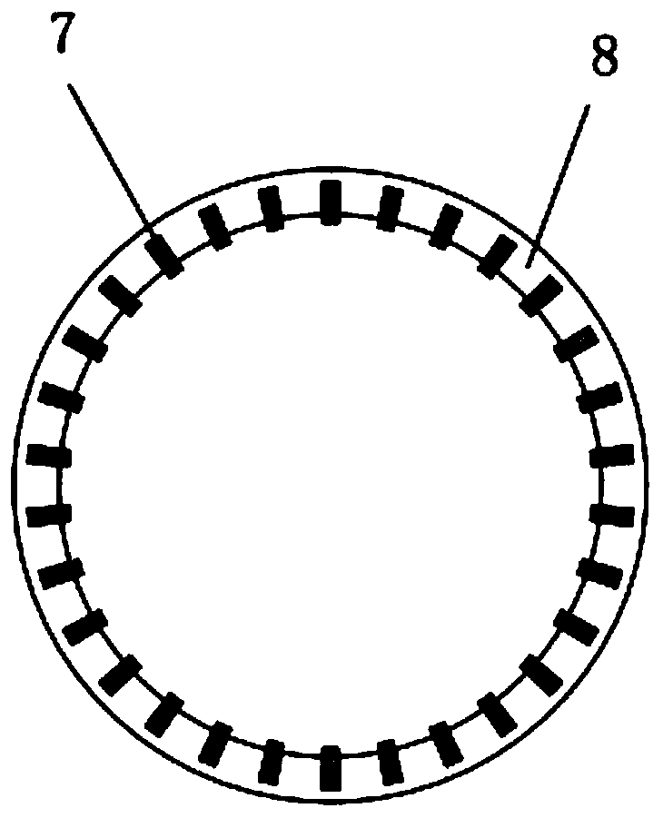
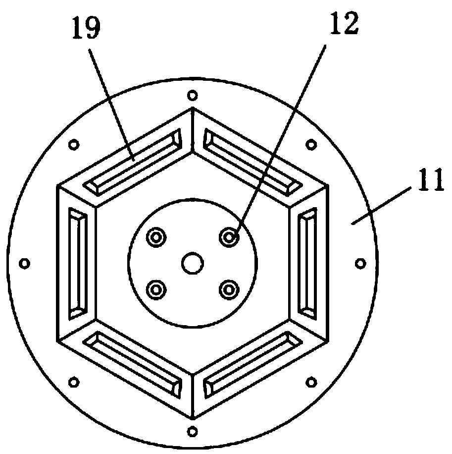
[0021] see Figure 1-7 , the present invention provides a technical solution: a cooling device for the inner wall of a wind power generating set, including an exhaust tube 1, the exhaust tube is fixedly connected with the upper surface of the wind power generating set tower through screws, and the lower end of the exhaust tube Through the upper surface of the wind turbine tower, the outer side of the upper opening of the exhaust tube is provided with an inner ...


PUM


Abstract

The invention discloses a heat radiating device of an inner wall of a wind turbine generator system. A whole is formed through an air discharging barrel, a filtering net, a stopping cover, an upper fixing ring, a vertical air guide plate, a horizontal air guide plate and a lower fixing ring, high temperature air at the upper portion of a tower of the wind turbine generator system is discharged outfrom the air discharging barrel, and foreign matter or rainwater and the like are prevented from entering the device; a supporting frame, a fan motor and a fan impeller are matched so that the high temperature air in the tower of the wind turbine generator system can flow to the air discharging barrel along an air guide opening to be discharged out, and the heat radiating effect can be achieved;and in addition, the effect of replacing air in a liquid discharging pipe and a flow dividing pipe is achieved, the air flowing upwards can be brought away through partial heat of the inner side of the tower of the wind turbine generator system, and the heat radiating effect is strengthened. By means of the heat radiating device, the high temperature air at the upper portion of the tower of the wind turbine generator system can be directly discharged out from the upper portion, the heat inside the tower of the wind turbine generator system can be brought away, the heat radiating efficiency ishigh, the structure is simple, and the overhauling, dismounting and mounting are convenient.

Description

technical field [0001] The invention relates to the technical field of wind power generation, and specifically relates to a cooling device for the inner wall of a wind power generating set. Background technique [0002] Many devices in the wind power generating set will emit a large amount of heat after running for a certain period of time, which will increase the temperature inside the tower of the wind power generating set and affect the normal operation of the equipment. The heat dissipation device of the existing wind power generating set transports the external ambient air to the heating equipment through the air duct, so that the air in the air duct will take away the heat around the heating equipment to achieve the effect of cooling the heating equipment, but the heat generated by the equipment As a result, the hot air can spread to the inside of the tower in a large range, and the heat dissipation efficiency of the existing heat dissipation device is still low. Con...

Claims


Application Information

Patent Timeline
Patent Type & Authority Applications(China)
IPC IPC(8): F03D80/60F03D80/00F03D17/00F03D13/20
CPCF03D13/20F03D17/00F03D80/00F03D80/60Y02E10/72Y02E10/728
Inventor 魏宪甲陈遂永叶克兵
Owner 十堰善新新能源科技有限公司
Learn More