Gas firefighting explosive-proof valve

A gas and fire-fighting technology, which is applied in the direction of lifting valves, valve details, valve devices, etc., can solve problems affecting dust transportation, etc., and achieve the effects of avoiding valve disc damage, increasing sealing, and avoiding secondary explosions

Inactive Publication Date: 2018-11-20
HENAN YUNLE TECH CO LTD
View PDF1 Cites 0 Cited by
  • Summary
  • Abstract
  • Description
  • Claims
  • Application Information

AI Technical Summary

Problems solved by technology

[0004] Based on the above technical problems, the present invention provides a gas fire-proof explosion-proof valve

Method used


Image

  • Gas firefighting explosive-proof valve
  • Gas firefighting explosive-proof valve
  • Gas firefighting explosive-proof valve

Examples


Embodiment 1

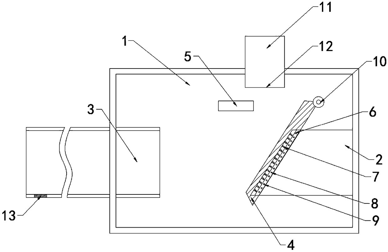
[0036] A gas fire-fighting explosion-proof valve, comprising a housing 1, the two ends of the housing 1 are respectively provided with a feed pipe 2 and a discharge pipe 3, and a valve flap 4 for opening and closing the feed pipe 2; one end of the valve flap 4 A rotating shaft 10 is provided, and the valve disc 4 can rotate around the rotating shaft 10 to realize the opening and closing of the feed pipe 2; the valve disc 4 is made of metal magnetic material, and the inner wall of the housing 1 is provided with a magnet 5 that can absorb the valve disc 4,

[0037] The housing 1 is provided with a gas fire-fighting mechanism 11 on the upper part of the valve flap 4, and the lower part of the gas fire-fighting mechanism 11 is provided with an air outlet 12, and the gas outlet 12 is located above the valve flap 4; The temperature sensor 13, the temperature sensor 13, and the gas fire-fighting mechanism 11 are all connected with the control system.

Embodiment 2

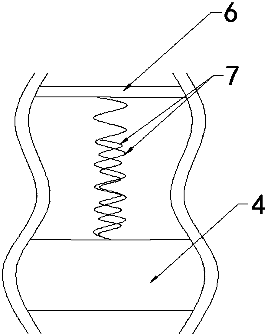
[0039]This embodiment is further optimized based on Embodiment 1. The valve disc 4 is located at the contact position with the feed pipe 2 and is provided with a buffer plate 6, and a plurality of buffer devices are arranged between the buffer plate 6 and the valve disc 4; each buffer device It includes a plurality of coaxially arranged springs 7, and the heights of the plurality of springs 7 in the same buffer device are all different;

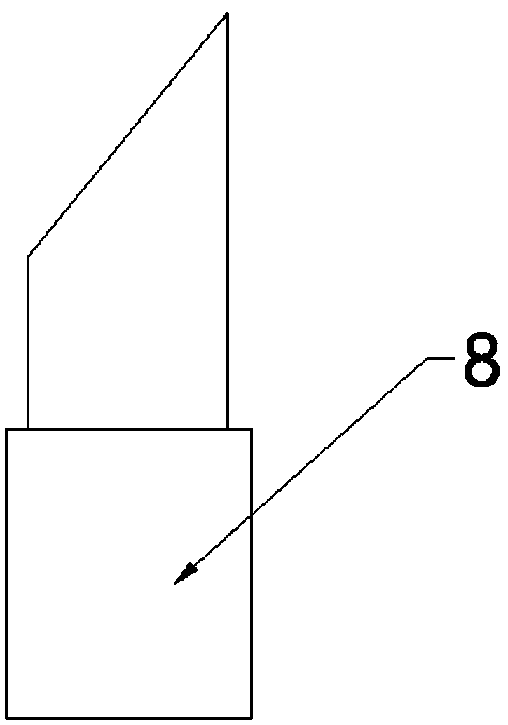
[0040] The feed pipe 2 is provided with a plurality of elastic rods 8 on the outer circumferential surface of one end of the valve disc 4, and a plurality of fixing holes 9 are arranged on the valve disc 4 corresponding to the positions of the elastic rods 8, and the elastic rods 8 cooperate with the fixing holes 9 to hold the valve disc 4 is connected with feed pipe 2;

[0041] The top of the elastic rod 8 is an inclined surface, and the inclined surface is arranged on one side of the valve flap 4, so that the elastic rod 8 is pressed down d...

Embodiment 3

[0045] This embodiment is further optimized based on Embodiment 2. The fixing hole 9 is a through hole, so that when the valve disc 4 is separated from the feed pipe 2, it can directly pass through the fixing hole 9, and the elastic material stuck in the fixing hole 9 can be directly passed through the fixing hole 9. The rod 8 shrinks, thereby facilitating the separation of the valve disc 4 and the feed pipe 2 .


PUM


Abstract

The invention relates to the technical field of gas firefighting, and discloses a gas firefighting explosive-proof valve. The gas firefighting explosive-proof valve comprises a shell; a feeding pipe,a discharging pipe and a valve clack are arranged at the two ends of the shell correspondingly; the valve clack is made of a metal magnetic material; a magnet capable of attracting the valve clack isarranged on the inner wall of the shell; a gas firefighting mechanism is arranged on the position, above the valve clack, of the shell, and a gas outlet is formed in the lower portion of the gas firefighting mechanism and located above the valve clack; a temperature sensor is arranged at the end, opposite to the valve clack, of the discharging pipe; and the temperature sensor and the gas firefighting mechanism are connected with a control system. Firefighting gas can extinguish a fire, during an explosion, the temperature sensor detects that the temperature is increased, then the control system controls the firefighting mechanism to release the firefighting gas into the shell, the firefighting gas impacts the valve clack, thus the valve clack rotates to be closed with the feeding pipe, therefore, the valve clack can be horizontally placed during normal working, and dust transporting is prevented from being affected.

Description

technical field [0001] The invention relates to the technical field of gas fire protection, in particular to an explosion-proof valve for gas fire protection. Background technique [0002] At present, dust explosions are prone to occur in grain and agricultural product dust, metal dust, coal powder, pharmaceutical engineering powder, petrochemical dust, textile industrial fiber, wood processing and other industries. With the continuous expansion of production scale and the development of fine powder processing, dust explosion accidents in my country are showing a trend of frequent occurrence. On August 2, 2014, Jiangsu Kunshan Zhongrong Metal Products Co., Ltd. had a particularly serious aluminum dust explosion accident, which eventually resulted in 146 deaths, 258 injuries, and a direct economic loss of 351 million yuan. In order to prevent the occurrence of fire and explosion accidents, relevant state departments require these workplaces to take strict explosion-proof mea...

Claims


Application Information

Patent Timeline
IPC IPC(8): F16K1/226F16K1/36F16K47/04F16K31/66
CPCF16K1/2261F16K1/36F16K31/002F16K47/045
Inventor 金鹏
Owner HENAN YUNLE TECH CO LTD
Why Eureka
Try Eureka