An oil return structure and its ascending steam return standpipe oil return device

A riser and pipeline technology, applied in the field of oil return structure and its rising steam return riser oil return device, can solve problems such as difficulty in oil return, and achieve the effect of ensuring oil return efficiency, compact structure and high oil return efficiency

Active Publication Date: 2021-08-24
广州市粤联水产制冷工程有限公司
View PDF0 Cites 0 Cited by
  • Summary
  • Abstract
  • Description
  • Claims
  • Application Information

AI Technical Summary

Problems solved by technology

[0004] The embodiment of the present invention discloses an oil return structure and its ascending steam return standpipe oil return device, which has a compact structure and solves the problem of difficult oil return caused by large thermal load fluctuations in the refrigeration system

Method used


Image

  • An oil return structure and its ascending steam return standpipe oil return device
  • An oil return structure and its ascending steam return standpipe oil return device
  • An oil return structure and its ascending steam return standpipe oil return device

Examples


Embodiment 1

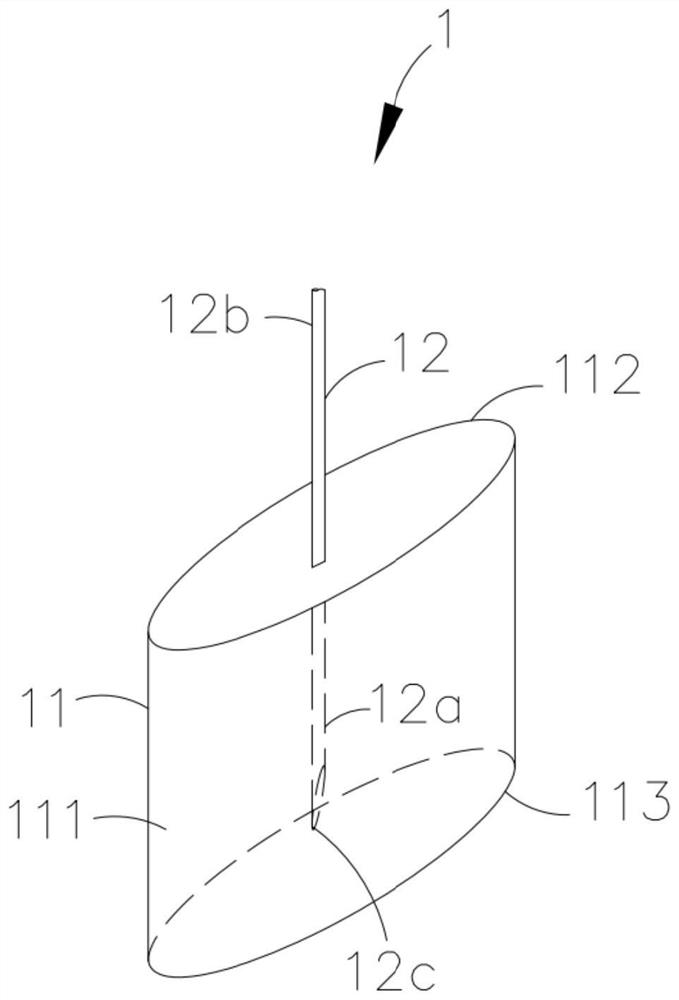
[0044] Please also refer to Figure 1 to Figure 2 , an oil return structure 1 provided by the present invention, the oil return structure 1 includes a first device 11 and at least one standpipe 12, the nozzle 12c of the first end 12a of the standpipe 12 is an oblique opening, and the standpipe The first end 12a of 12 extends into the accommodating chamber 111 and is fixed in the accommodating chamber 111, and the oblique opening is completely located in the accommodating chamber 111, and the standpipe 12 is used to transport the fluid in the accommodating chamber 111 .

[0045] Wherein, the nozzle 12c of the first end 12a of the standpipe 12 is oblique, that is, the length direction of the standpipe 12 is not perpendicular to the cross section of the nozzle 12c of the standpipe 12 . The bevel can be formed by cutting the first end 12a of the riser 12 at a certain oblique angle. The effect of setting the bevel is that since the bevel is not flat, when the standpipe 12 is arra...

Embodiment 2

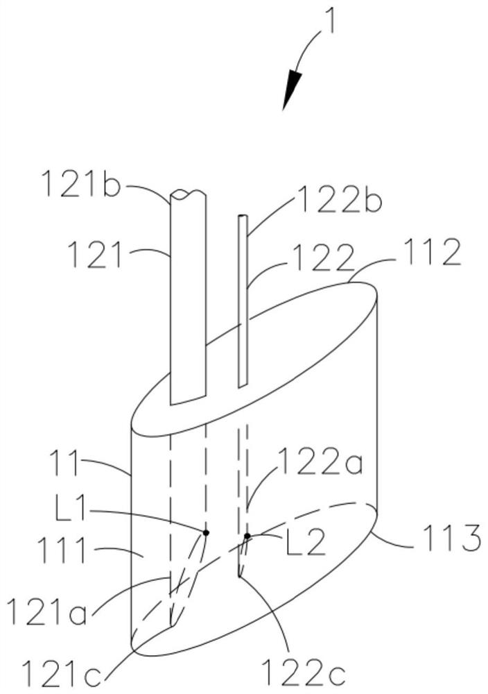
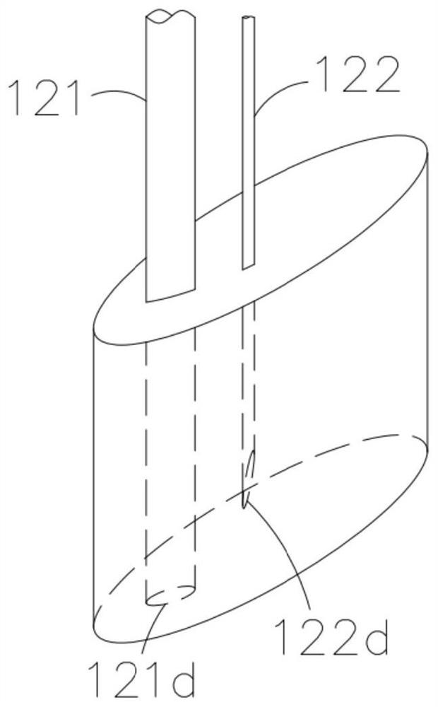
[0058] Embodiment 2 of the present invention provides an oil return structure. The difference between this oil return structure and the oil return structure in Embodiment 1 is that when there are multiple standpipes, take the case of two standpipes as an example (such as image 3 shown), the two standpipes can be respectively the first riser 121 and the second riser 122, the first standpipe 121 and the second standpipe 122 are arranged at intervals, and the nozzle 121d of the first riser 121 is a flat mouth, The nozzle 122d of the second riser 122 is an oblique opening.

[0059] The oil return structure provided by Embodiment 2 of the present invention adopts the method that some risers are arranged with flat openings, and some of the risers are arranged with inclined openings, which can reduce the production of inclined opening risers, and the risers with flat openings can be recycled for other In the application occasion, the utilization rate of the equipment is improved.

Embodiment 3

[0061] see Figure 4 , which is a structural schematic diagram of an oil return device for an ascending return steam riser provided by the present invention. The rising steam riser oil return device can be applied to a refrigeration system, the refrigeration system includes an evaporator 5 and a compressor 6, and the rising steam riser oil return device includes a first pipeline 2, a second pipeline 3 and an oil return structure 1.

[0062] Wherein, the oil return structure 1 is the oil return structure 1 as described in the first embodiment. For the specific structural design of the oil return structure 1, please refer to the first embodiment, which will not be repeated here.

[0063] Wherein, one end of the first pipeline 2 is connected to the evaporator 5, the other end of the first pipeline 2 communicates with the accommodating cavity 111 of the first device 11 of the oil return structure 1, and one end of the second pipeline 3 is connected to the return The second end 1...


PUM


Abstract

The invention discloses an oil return structure, which comprises a first component and at least one standpipe. The first component is a sealing structure with an accommodating cavity. One end extends into the accommodating cavity and is fixed in the accommodating cavity, and the oblique opening is completely located in the accommodating cavity, and the standpipe is used for conveying the fluid in the accommodating cavity. The present invention also provides an oil return device for rising return steam standpipe, which includes a first pipeline, a second pipeline and an oil return structure, the first pipeline is used to store the fluid delivered from the evaporator, and Under the action, a pressure difference is formed at both ends of the first pipeline, so that the fluid flows from the first pipeline to the accommodating cavity and the riser in sequence under the action of the pressure difference, and finally flows into the second pipeline. The oil return structure and the oil return device of the ascending steam return standpipe provided by the present invention are compact in structure and can achieve the purpose of efficient oil return.

Description

technical field [0001] The invention relates to the technical field of refrigeration, in particular to an oil return structure and an oil return device for an ascending steam return standpipe. Background technique [0002] In the fluorine refrigeration system, part of the lubricating oil of the compressor will be discharged from the compressor together with the refrigerant liquid, and then enter the evaporator, condenser or piping of the system, only the discharged lubricating oil can be brought back smoothly In order to maintain the dynamic oil balance of the entire system, the system will cause problems such as operational failure or damage to the compressor due to lack of oil. The process of lubricating oil from being discharged to returning to the compressor is called oil return, and the normal operation of the oil return process is especially important for fluorine refrigeration systems. [0003] At present, the fluorine refrigeration system adopts the method of return...

Claims


Application Information

Patent Timeline
Patent Type & Authority Patents(China)
IPC IPC(8): F25B43/02F25B31/00
CPCF25B31/004F25B43/02
Inventor 陈炳耀吴少强
Owner 广州市粤联水产制冷工程有限公司
Why Eureka
Try Eureka