Adhesive drying machine

A drying machine and glue technology, applied in the direction of non-progressive drying machines, drying machines, drying solid materials, etc., can solve the problems of affecting processing efficiency and low drying efficiency, and achieve the effect of improving processing efficiency and drying efficiency

Inactive Publication Date: 2018-11-20
梁林燕
View PDF0 Cites 0 Cited by
  • Summary
  • Abstract
  • Description
  • Claims
  • Application Information

AI Technical Summary

Problems solved by technology

[0004] The purpose of the present invention is to solve the shortcomings in the prior art, such as: the glue dryer only rotates in a single direction to accelerate drying during drying, resulting in low drying efficiency, which greatly affects the normal processing efficiency, and A Glue Dryer Proposed

Method used


Image

  • Adhesive drying machine
  • Adhesive drying machine

Examples


Embodiment Construction

[0018] The technical solutions in the embodiments of the present invention will be clearly and completely described below with reference to the accompanying drawings in the embodiments of the present invention. Obviously, the described embodiments are only a part of the embodiments of the present invention, but not all of the embodiments.

[0019] In the description of the present invention, it should be understood that the terms "upper", "lower", "front", "rear", "left", "right", "top", "bottom", "inside", " The orientation or positional relationship indicated by "outside" is based on the orientation or positional relationship shown in the accompanying drawings, and is only for the convenience of describing the present invention and simplifying the description, rather than indicating or implying that the indicated device or element must have a specific orientation, so as to The specific orientation configuration and operation are therefore not to be construed as limitations of...


PUM


Abstract

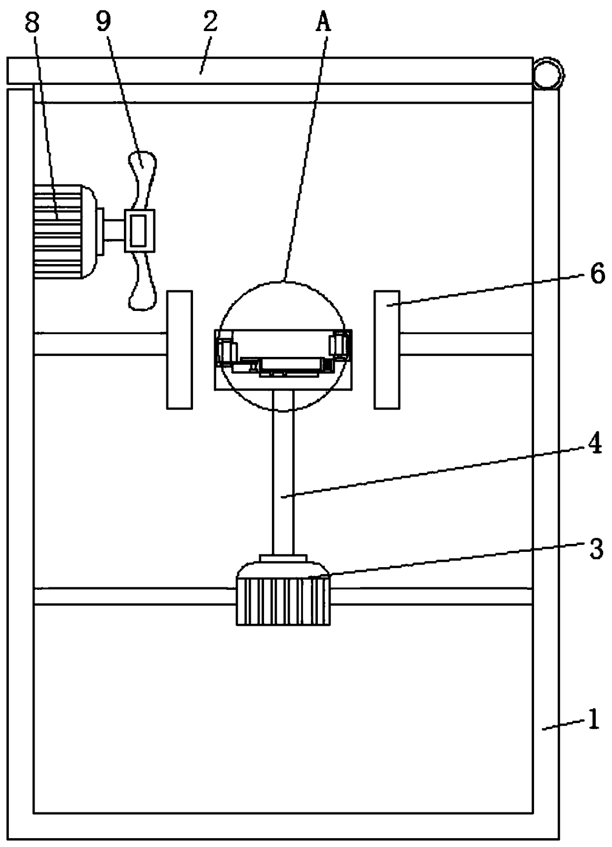
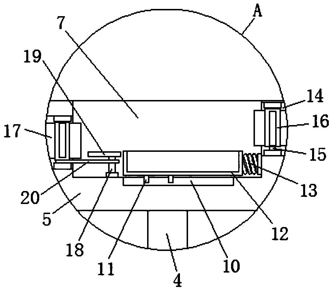
The invention discloses an adhesive drying machine which comprises a machine body, wherein a machine cover is movably connected with the top of the machine body through a hinge part; a driving motor is fixedly connected onto the inner walls of the left and right sides of the machine body through a connecting rod; a rotating rod is fixedly connected with the output end at the top of the driving motor; a rotating disc is fixedly connected with the top end of the rotating rod; heating plates being positioned on two sides of the rotating disc and symmetric to each other are fixedly connected on tothe inner walls of the left and right sides of the machine body through combining rods; and a mounting groove is formed in the top of the rotating disc. The adhesive drying machine disclosed by the invention has the beneficial effects that through the arrangement of an impeller, a rotating rod and a transmission belt, the transmission effect generated by utilizing the rotating inertia can be achieved; through the arrangement of a reset spring and a sliding rod, an accommodating tank can be subjected to stress and can perform reciprocating action as well as the drying process can be accelerated; through the reciprocating action performed by utilizing the inertia and the acceleration of the drying process, the drying efficiency can be improved; and accordingly, the overall processing efficiency can be improved.

Description

technical field [0001] The invention relates to the technical field of dryers, in particular to a glue dryer. Background technique [0002] Dryer refers to a mechanical device that uses heat energy to reduce the moisture content of materials. It is used to dry objects. The dryer vaporizes and overflows the moisture in the materials through heating to obtain solid materials with a specified moisture content. The purpose of drying is to For the needs of material use or further processing, glue refers to an oral preparation that uses animal skin, bone, nails and horns as raw materials, decocts the glue with water, and concentrates it into a dry glue. Its main components are animal hydrolyzed protein substances. And add a certain amount of sugar, oil and wine (rice wine) and other accessories. [0003] With the increasing use of glues, the processing output of glues is also increasing, and the requirements for glue dryers are also increased. However, the existing glue dryers on...

Claims


Application Information

Patent Timeline
IPC IPC(8): F26B11/00F26B21/00F26B25/00
CPCF26B11/00F26B21/00F26B25/00
Inventor 梁林燕
Owner 梁林燕
Why Eureka
Try Eureka