

A High Precision Zero Temperature Drift Regulator Circuit With Adjustable Reference Voltage
A technology of reference voltage and voltage regulator, applied in the direction of instruments, regulating electrical variables, control/regulating systems, etc., can solve the problem of inability to modify, and achieve the effect of improving circuit performance and reducing design difficulty
- Summary
- Abstract
- Description
- Claims
- Application Information
AI Technical Summary
Problems solved by technology
Method used
Image



Examples
Embodiment Construction
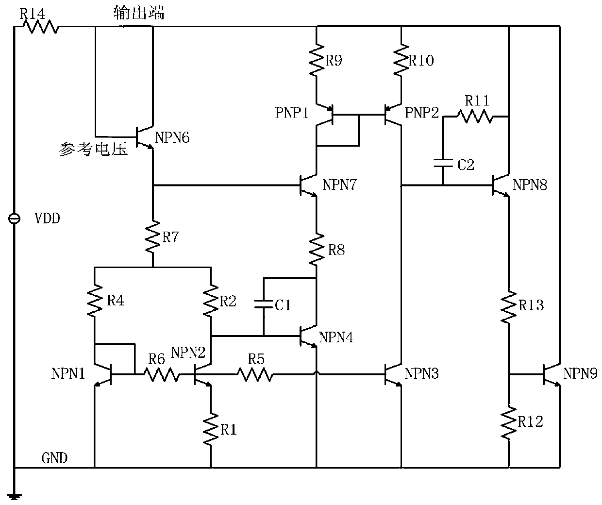
[0012] Such as figure 1 , The VDD voltage source is added to one end of the R14 resistor, and the other end of the voltage source is grounded. VDD can take any value between 3 and 40V. The reference voltage is shorted to the output terminal, and the other end of the resistor R14 is connected to the output terminal. At this time, the circuit will enter a normal working state, and the output terminal after current limiting through the resistor R14 is equal to the reference voltage. When R6=0, the collector current ratio of PNP1 and PNP2 is 1:1, so the collector current ratio of NPN3 and NPN4 is 1:1, according to the formula VBE=VT*ln(Ic / Is), VBE is the transistor NPN6 The emitter junction conduction voltage, VT is the thermal voltage, Ic is the collector current of the triode NPN6, and Is is the saturation current of the triode NPN6. According to the formula, VBE3 of NPN3 is equal to VBE4 of NPN4, so the base of NPN3 is at the same potential as the base of NPN4, ignoring the in...
PUM
 Abstract
Description
Claims
Application Information