Method for identifying structure distributed dynamic load based on multi-source uncertainty

An uncertainty and dynamic load technology, applied in special data processing applications, instruments, electrical digital data processing, etc., can solve problems such as instrument measurement errors, information transmission interference, and uncertainty of dynamic load identification problems, and reduce costs , efficient identification, and strong engineering practicability

Active Publication Date: 2018-11-20
BEIHANG UNIV
View PDF10 Cites 15 Cited by
  • Summary
  • Abstract
  • Description
  • Claims
  • Application Information

AI Technical Summary

Problems solved by technology

[0004] In addition, for general engineering practice, there will be many uncertain factors in the measurement process of structural dynamic response, including static uncertainties including engineering structure processing, manufacturing, installation errors, material performance discreteness, modeling errors, etc., and The dynamic uncertainties including instrument measurement error and information transmission interference make the dynamic load identification problem an uncertain problem. Uncertainty parameters in the modeling process mainly include measurement information, structural parameters, geometric properties, dynamic Load action point and action direction, initial conditions and boundary conditions, etc.

Method used


Image

  • Method for identifying structure distributed dynamic load based on multi-source uncertainty
  • Method for identifying structure distributed dynamic load based on multi-source uncertainty
  • Method for identifying structure distributed dynamic load based on multi-source uncertainty

Examples


Embodiment 1

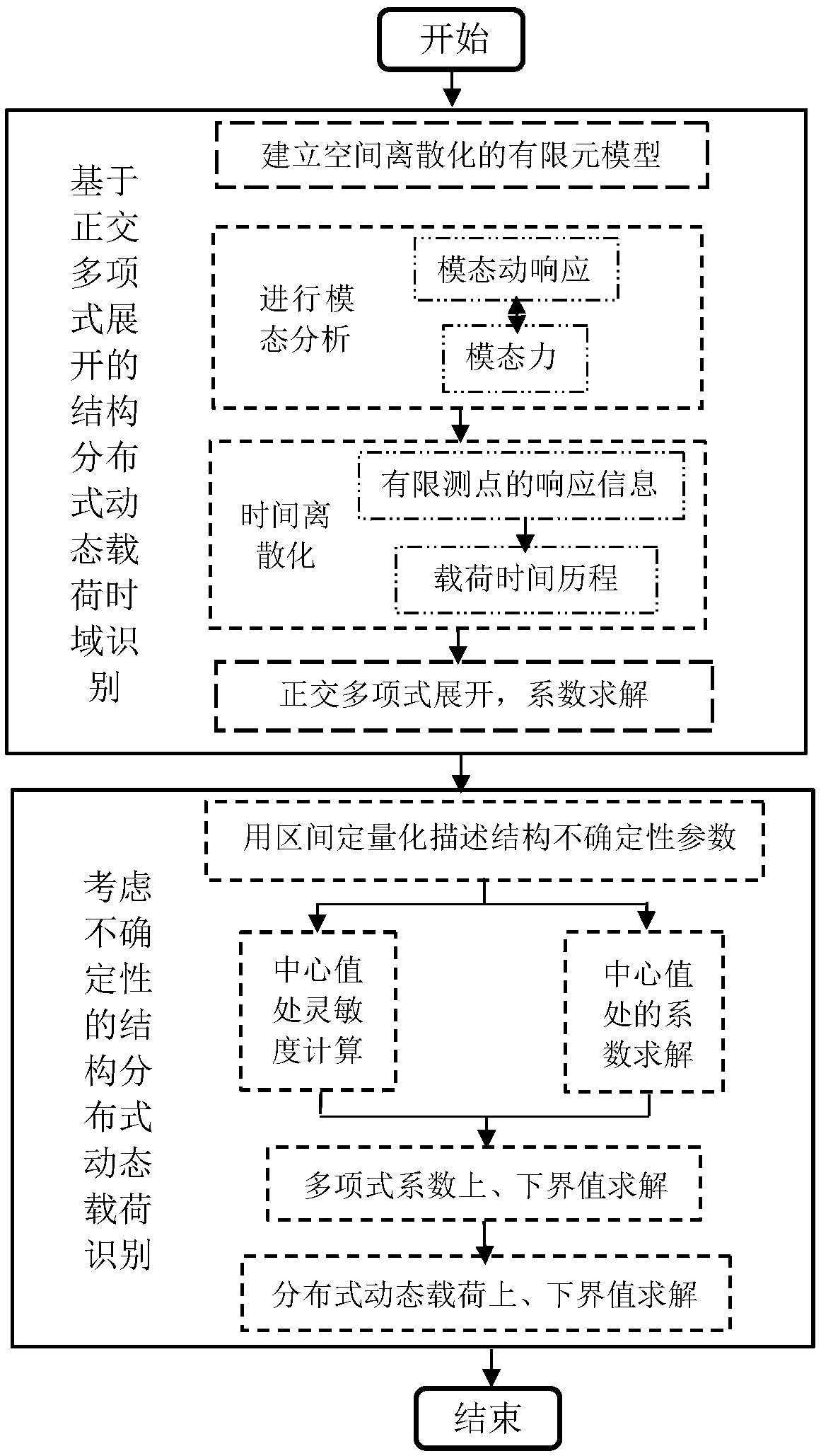
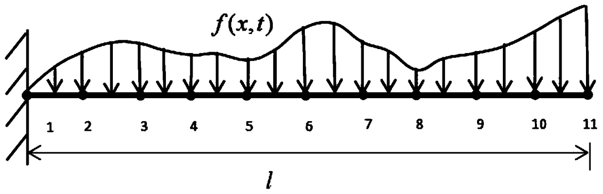
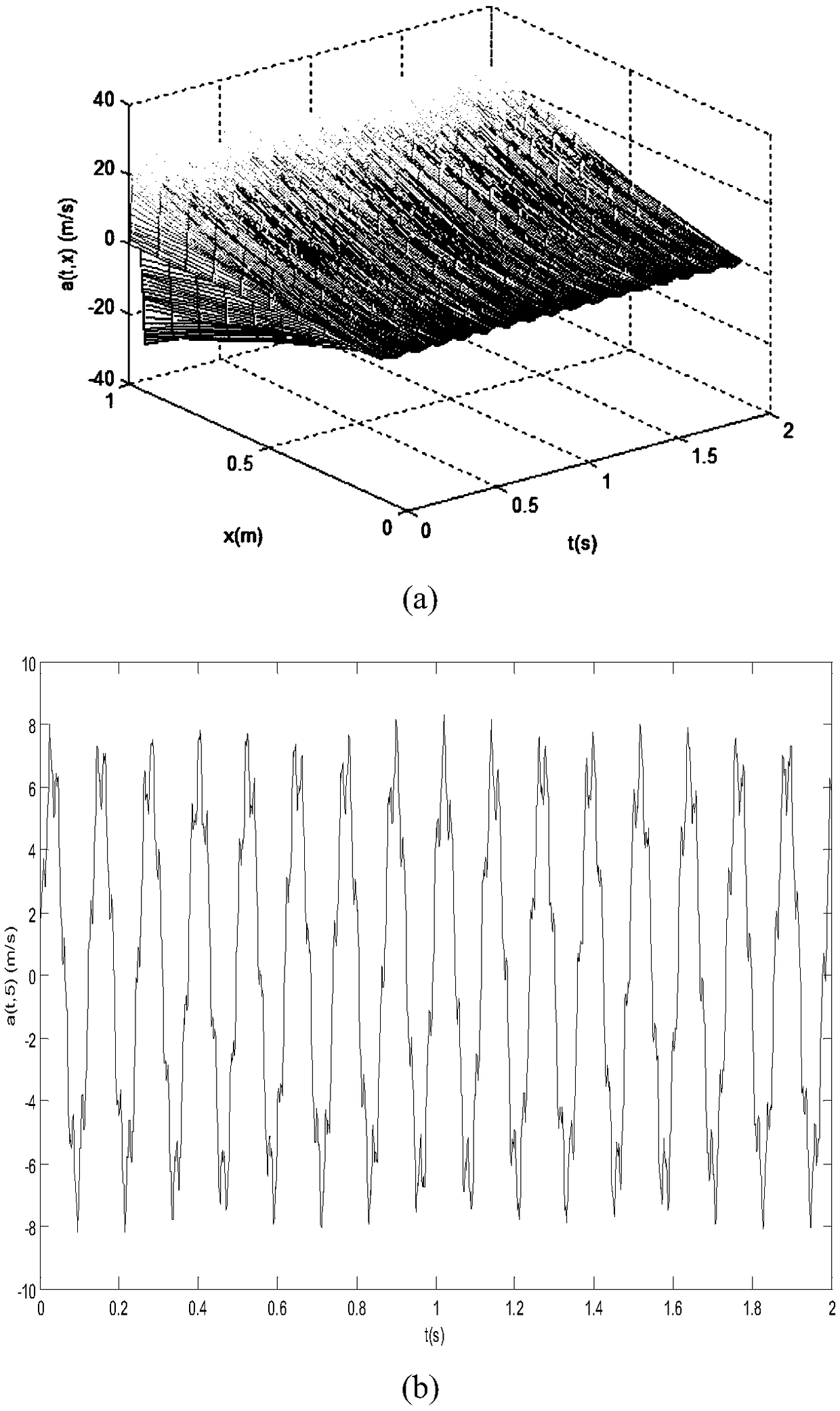
[0048] The spatially discretized finite element model of the cantilever beam structure is as follows figure 2 As shown, the initial parameters of the calculation model are set as follows: beam length l=1m, cross-section is square and side length is 0.01m, elastic modulus is 150GPa, density is 6000kg / m 3 , ignoring the damping of each order of the system, assuming that the dynamic load acting vertically on the cantilever beam is a uniform load: f(x,t)=50t(N), the sampling interval is [0,2]s, and the time interval is 0.01s , take the 5th-order generalized Chebyshev orthogonal polynomial to carry out the load identification in the time domain, divide the beam into 10 finite element elements, with a total of 11 nodes, regardless of the nodes at the fixed end of the cantilever beam, the entire beam element has a total of 30 degrees of freedom, take 10 measurement points on the beam, and measure the acceleration response at each point, assuming that the modal order after truncation...

Embodiment 2

[0054] The spatially discretized finite element model of the cantilever beam structure is as follows figure 2 As shown, the initial parameters of the model are set as follows: the beam length l=2m, the cross section is square and the side length is 0.02m, the median value of elastic modulus is 200GPa, and the median value of density is 5000kg / m 3 , ignoring the damping of each order of the system, assuming that the dynamic load acting vertically on the cantilever beam is a simple harmonic load: f(x,t)=200sin(2.5πxt)(N), the sampling interval is [0,1.5]s, the time The interval is 0.01s, and the 6th-order generalized Chebyshev orthogonal polynomial is used to identify the load in the time domain. The beam is divided into 10 finite element elements, with a total of 11 nodes. Regardless of the nodes at the fixed end of the cantilever beam, the entire beam The unit has a total of 30 degrees of freedom, and 10 measurement points are taken on the beam to measure the acceleration res...


PUM


Abstract

The invention discloses a method for identifying a structure distributed dynamic load based on multi-source uncertainty. According to the method, the structural uncertainty parameters of a structure are considered, and based on a load identification method in a time domain, combined with an orthogonal polynomial and a TIAM algorithm, the distributed dynamic load of the structure is identified. Themethod comprises a step of establishing a distributed dynamic load identification model of a deterministic structure based on the time domain method and approximating a dynamic distributed load by the orthogonal polynomial, a step of quantitatively describing the uncertainty parameter of the structure by an interval, converting a dynamic load identification problem of the structure into two kindsof deterministic problems by using the TIAM algorithm, and finally obtaining upper and lower bounds of the dynamic load borne by the uncertainty structure.

Description

technical field [0001] The invention relates to the technical field of structural dynamics inverse problems, in particular to a method for identifying structural distributed dynamic loads based on multi-source uncertainties. Background technique [0002] With the continuous development of science and technology, modern engineering puts forward higher and stricter requirements on the vibration reliability of structures. Whether it is the dynamic response analysis, dynamic strength analysis, or structural optimization design of engineering structures, etc., all depend on the dynamic loads borne by the structure. The dynamic load is also the vibration source in the vibration process. It is the initial input parameter and the source of various vibrations. The acquisition of the vibration source, that is, the determination of the dynamic load on the structure is becoming more and more important. Only by providing accurate and reliable loads can it be possible to apply various ad...

Claims


Application Information

Patent Timeline
Patent Type & Authority Applications(China)
IPC IPC(8): G06F17/50
CPCG06F30/23G06F2119/06
Inventor 王磊刘亚儒刘易斯
Owner BEIHANG UNIV
Why Eureka
Try Eureka