
Cervical lesion detector and detection method

A technology for cervical lesions and cervix, which is applied in the field of medical equipment, can solve the problems of unguaranteed accuracy, high price and dependence of HPV inspection, achieve accurate control of sampling force and number of laps, realize single-handed automatic operation, and increase friction Effect

Pending Publication Date: 2018-11-23
康涛
View PDF0 Cites 2 Cited by
  • Summary
  • Abstract
  • Description
  • Claims
  • Application Information

AI Technical Summary

Problems solved by technology

First of all, the cost of TCT examination is high, the result is slow, and the accuracy rate cannot be guaranteed. At the same time, it depends on pathologists. In my country, pathologists are quite scarce and cannot meet the demand; secondly, the price of HPV examination is more expensive, and the time to produce results is slower, and the test is positive. The rate is too high, but the absolute majority of HPV virus infections are transient, and more than 90% can be cleared by autoimmunity, so HPV inspection is more likely to cause psychological burden on patients and the referral rate of colposcopy; the cost of colposcopy is relatively low More expensive, and the operation is complicated, time-consuming, professional requirements are high, the patient is more uncomfortable during the examination, and depends on colposcopy equipment (more expensive)

Method used


Image

  • Cervical lesion detector and detection method
  • Cervical lesion detector and detection method
  • Cervical lesion detector and detection method

Examples


Embodiment 1

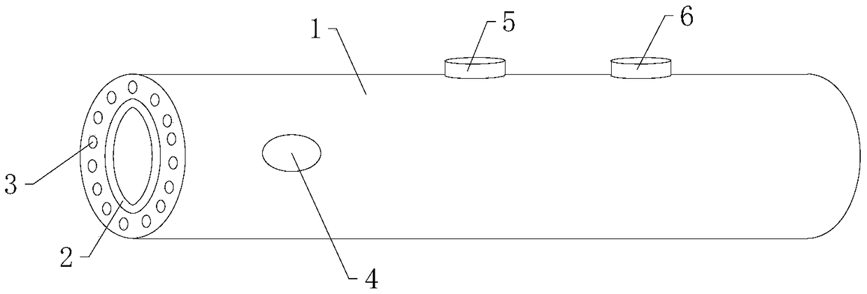
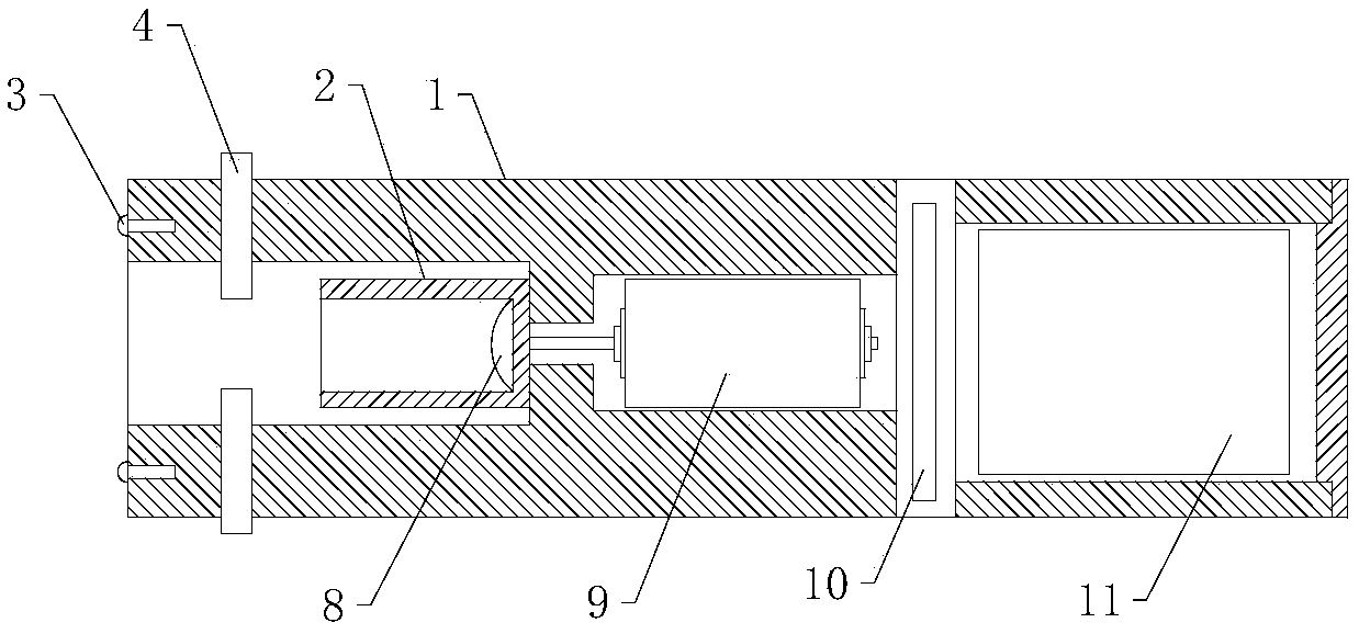
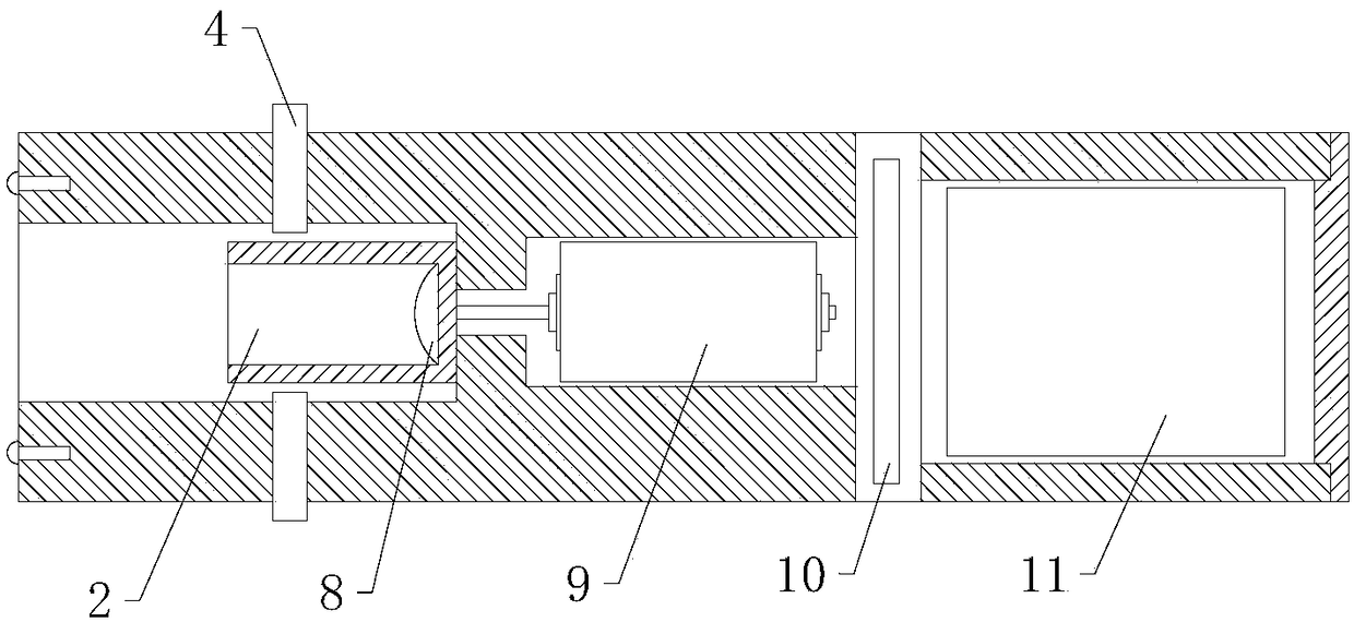
[0040] Such as figure 1 , figure 2 As shown, this embodiment discloses a cervical lesion detector, including a pressure power device and a probe 12 . Specifically, the pressure power device includes a holding main body 1, a base hole is provided at the front end of the holding main body, a transmission sleeve 2 that rotates relative to it is provided in the base hole, and a wireless pressure sensor is provided at the bottom of the transmission sleeve. 8. The motor 9 that drives the transmission sleeve is also provided in the holding body, and the main board 10 that controls the operation of the motor; the probe rod includes a probe shaft 1201 that cooperates with the transmission sleeve, and the front end of the probe shaft is provided with a conical probe Head 1202, the rear end of the probe shaft can be inserted into the sleeve and apply pressure to the wireless pressure sensor.

[0041] Such as Figure 4 , Figure 5As shown, the above scheme is optimized, the probe hea...

Embodiment 2

[0057] This embodiment discloses a cervical lesion detector, which includes a pressure power device and a detection rod. Specifically, the pressure power device includes a holding main body, a base hole is provided at the front end of the holding main body, a transmission sleeve that rotates relative to it is provided in the base hole, and a wireless pressure sensor is provided at the bottom of the transmission sleeve; The main body of the grip is also provided with a motor for driving the transmission sleeve and a main board for controlling the operation of the motor; the probe rod includes a probe shaft that cooperates with the drive sleeve, the front end of the probe shaft is provided with a tapered probe head, and the rear end of the probe shaft The end can be inserted into the sleeve and apply pressure to the wireless pressure sensor.

[0058] The difference between this embodiment and embodiment 1 is:

[0059] Such as Figure 7 As shown, in this embodiment, the chute i...

Embodiment 3

[0063] This embodiment discloses a cervical lesion detector, which includes a pressure power device and a detection rod. Specifically, the pressure power device includes a holding main body, a base hole is provided at the front end of the holding main body, a transmission sleeve that rotates relative to it is provided in the base hole, and a wireless pressure sensor is provided at the bottom of the transmission sleeve; The main body of the grip is also provided with a motor for driving the transmission sleeve and a main board for controlling the operation of the motor; the probe rod includes a probe shaft that cooperates with the drive sleeve, the front end of the probe shaft is provided with a tapered probe head, and the rear end of the probe shaft The end can be inserted into the sleeve and apply pressure to the wireless pressure sensor.

[0064] The difference between this embodiment and embodiment 1 is:

[0065] Such as figure 2 , image 3 , Figure 8 As shown, the ho...


PUM


Abstract

The invention belongs to the technical field of medical devices, and discloses a cervical lesion detector which comprises a pressure power device and a detection bar. The pressure power device comprises a holding body, a base hole is formed in the front end of the holding body, a transmission sleeve is arranged in the base hole and rotates relative to the base hole, a wireless pressure sensor is arranged at the bottom of the transmission sleeve, a motor and a main board are arranged in the holding body, the motor is used for driving the transmission sleeve, the main board is used for controlling the motor to run, the detection bar comprises a detection shaft matched with the transmission sleeve, a conical detection head is arranged at the front end of the detection shaft, the rear end of the detection shaft can be inserted into a sleeve, and the pressure is applied to the wireless pressure sensor. According to the detector, a clinician can independently judge and read a result in cervical lesions detection, and the detector is bedside, easy to operate, low in cost, short in time and suitable for popularization and use and solves awkward situations in domestic cervical cancer screening of women.

Description

technical field [0001] The invention belongs to the technical field of medical equipment, and in particular relates to a cervical lesion detector and a method for detecting it. Background technique [0002] Cervical cancer is the second largest gynecological tumor in the world. There are about 131,500 new cases in my country every year, accounting for 1 / 4 of the world's total. More than 50,000 women die of cervical cancer in my country every year. According to the sixth census data of the National Bureau of Statistics of my country, there are about 430 million women aged 21 to 65 in China. Since 2009, my country has started to implement the cervical cancer screening project for rural women and so far, only 60 million have been completed. The main reason is that the current examination methods are expensive, time-consuming, complicated to operate, very technically demanding, and rely on pathologists. [0003] The methods currently used for cervical lesion examination include...

Claims


Application Information

Patent Timeline
IPC IPC(8): A61B1/303A61B1/06A61B5/00
CPCA61B1/0684A61B1/303A61B5/4331
Inventor 康涛
Owner 康涛
Learn More