Shaping cutter for joint surgical operation

A technology of surgical operations and planing knives, which is applied in the fields of surgery, medical science, and anatomical instruments. It can solve problems such as unfavorable operations, insufficient sharp knife tooth structure, and impact on patient recovery, so as to avoid tearing and save operation time. , the effect of reducing the amount of surgical operations

Pending Publication Date: 2018-11-23
TIANYING PRECISION TOOL PANYU +1
0 Cites 3 Cited by

AI-Extracted Technical Summary

Problems solved by technology

[0003] In the prior art, planing tools for joint minimally invasive surgical instruments mostly focus on the overall structural design of the hollow outer tube in the cutting part of the planing tool and the inner tube in the corresponding window, and seldom involve the research on the serration of the cutting edge. The teeth of the planer are not sh...

Method used

Shown in Fig. 10 to Fig. 11 is the 3rd embodiment of joint surgery planer of the present invention, present embodiment is similar to embodiment one, and difference is that cutter tooth 3 is serrated The third knife-tooth window 33, the third knife-tooth window 33 includes a sawtooth surface 331 parallel to the axis of the inner tube 2 and a cut surface 332 perpendicular to the sawtooth surface 331, and several planer windows 4 are uniformly arranged around the head of the outer tube. When resecting tissues with complex angles, it can convenie...

Abstract

The invention relates to the technical field of endoscopic surgery tools, in particular to a shaping cutter for a joint surgical operation. The shaping cutter comprises an outer pipe and an inner pipewhich can rotate around the self axis and arranged into the outer pipe in a sleeved mode, the front end of the inner pipe is provided with cutter teeth used for rotatably cutting the tissue, and thefront end of the outer pipe is provided with at least one exposed shaping cutter window capable of containing at least part of cutter teeth; and the inner pipe is provided with a suction hole used forsucking cuttings by means of a negative pressure suction system, and one end of the inner pipe is connected with a power handle capable of controlling the inner pipe to rotate in the single way and in the reciprocating way. The cutter teeth are sharp, the cutting force in the operation process can be reduced, the phenomenon that the cutter teeth tear the uncut biological tissue is avoided, the degree of the secondary hurt of the operation to the affected part is reduced, and the pains of a patient are relieved; and multi-angle tissue or cartilage cutting and shaping operation can be conductedrapidly and conveniently when the tissue with the complex angle is cut off, and the operation time is saved.

Application Domain

Incision instrumentsEndoscopic cutting instruments

Technology Topic

Biological tissueSacroiliac joint +8

Image

  • Shaping cutter for joint surgical operation
  • Shaping cutter for joint surgical operation
  • Shaping cutter for joint surgical operation

Examples

  • Experimental program(4)

Example Embodiment

[0037] Example one
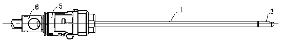
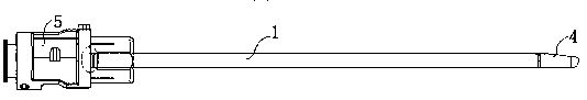
[0038] Such as Figure 1 to Figure 6 Shown is the first embodiment of the planing knife for joint surgery of the present invention. It includes an outer tube 1 and an inner tube 2 that can rotate around its axis and is sleeved in the outer tube. The front end of the inner tube 2 is provided for rotation. The knife teeth 3 for cutting tissues, the front end of the outer tube 1 is provided with at least one planer window 4 that can accommodate at least part of the exposed teeth; the inner tube 2 is provided with a suction hole for sucking chips through a negative pressure suction system, and the inner tube 2 One end of the tube is connected with a power handle that can control the one-way rotation and reciprocating rotation of the inner tube.
[0039] In the implementation of this embodiment, the one-way rotary motion and reciprocating rotary motion of the inner tube 2 are controlled by the power handle. The part of the inner tube 2 exposed on the outer tube 1 is rotated at a high speed to cooperate with the outer tube 1 to cut the tissue, and the cutting chips pass through The inner tube 2 is discharged from the body by means of a negative pressure suction system.
[0040] Specifically, the outer tube 1 is a first hollow tube, the front end of the first hollow tube is fixedly connected with the planer window 4, the rear end is embedded with a first handle 5; the first handle 5 is provided with a card slot; the inner tube 2 It is a second hollow tube. The front end of the second hollow tube is fixedly connected with the cutter teeth 3, and the rear end is embedded with a second handle 6; the second handle 6 is provided with a chuck that matches the slot. The inner tube 2 transmits power through the cooperation of the chuck and the slot to realize the one-way rotary movement and the reciprocating rotary movement of the inner tube 2. When the tissue is cut in both directions, a higher surgical efficiency can be obtained and the patient's pain can be reduced.
[0041] Among them, the cutter tooth 3 is a first cutter tooth window 31 in the shape of a melon seed. The first cutter tooth window 31 is formed by the intersection of a number of circles and the diameters of the circles are gradually along the axis of the inner tube from the front end of the inner tube to the rear end of the inner tube. The planer window 4 is a drop-shaped incision 41, and the edge of the first knife-tooth window 31 is set on the inner side of the edge of the drop-shaped incision 41; the melon seed-shaped first knife-tooth window 31 has better sharpness and reduces the operation The cutting force can avoid the tearing phenomenon of the uncut biological tissue by the planer, avoid the phenomenon of knife jam, and reduce the secondary damage of the operation to the affected area. During the operation, the part of the inner tube exposed on the outer tube cooperates with the outer tube to cut the tissue under high-speed rotation.

Example Embodiment

[0042] Example two
[0043] Such as Figure 7 to Figure 9 Shown is the second embodiment of the planing knife for joint surgery of the present invention. This embodiment is similar to the first embodiment, except that the tooth 3 is a second tooth window 32 with a crescent shape. The two-cut window 32 includes a chamfered surface 321 at the front end of the inner tube and a first section 322 perpendicular to the chamfered surface 321; the planer window 4 is a curved section 42 obtained by oblique cutting of the outer tube, and the second window 31 at least partially protrudes In the arc where the arc 42 is located. Cutting with the crescent-shaped second tooth window 32 can obtain a relatively flat and smooth cut surface. During the operation, the part of the inner tube 2 exposed on the outer tube 1 is rotated at a high speed to cooperate with the outer tube to cut the tissue.

Example Embodiment

[0044] Example three
[0045] Such as Figure 10 to Figure 11 Shown is the third embodiment of the planing knife for joint surgery of the present invention. This embodiment is similar to the first embodiment, except that the tooth 3 is a third tooth window 33 having a sawtooth shape. The three-tooth window 33 includes a serrated surface 331 parallel to the axis of the inner tube 2 and a cut surface 332 perpendicular to the serrated surface 331. A plurality of planer windows 4 are evenly arranged around the head of the outer tube. When removing complex angles of tissue, it can easily and quickly perform multi-angle tissue or cartilage cutting and planing operations, without the need to rotate the planer at too many angles, reducing surgical operations, improving surgical efficiency, and saving surgical time; in addition, these planing knife windows 4 It can also play a certain protective role to prevent the knife tooth 3 from excessively cutting the tissue. In this embodiment, there are three planer windows, and the three planer windows are distributed on the head of the outer tube 1 at an angle of 120° to each other.

PUM

no PUM

Description & Claims & Application Information

We can also present the details of the Description, Claims and Application information to help users get a comprehensive understanding of the technical details of the patent, such as background art, summary of invention, brief description of drawings, description of embodiments, and other original content. On the other hand, users can also determine the specific scope of protection of the technology through the list of claims; as well as understand the changes in the life cycle of the technology with the presentation of the patent timeline. Login to view more.

Similar technology patents

Corneal foreign body draw-out spoon

InactiveCN103006374Areduce workloadReduce secondary damage
Owner:尹澜

Surgical adsorption ligation device

PendingCN111528957Areduce bleedingImprove surgical efficiency
Owner:张云峰

Orbital endoscopic navigation surgery operation system based on eye tracker

PendingCN111759461AImprove surgical efficiency
Owner:SHANGHAI NINTH PEOPLES HOSPITAL AFFILIATED TO SHANGHAI JIAO TONG UNIV SCHOOL OF MEDICINE

Implanting device of artificial cochlea

ActiveCN113058156Areduce damageImprove surgical efficiency
Owner:FUDAN UNIV

Injected gas acidification method

InactiveCN111058823AIncrease productionReduce secondary damage
Owner:陕西博石源丰能源科技有限公司

Vaginal dilator for vagina tightening surgery

InactiveCN102319479ALarge operating spaceImprove surgical efficiency
Owner:THE SECOND AFFILIATED HOSPITAL OF THIRD MILITARY MEDICAL UNIV OF PLA

A measuring marker instrument used in laparoscopic surgery

PendingCN109222981AImprove convenienceImprove surgical efficiency
Owner:PEKING UNIV THIRD HOSPITAL

Classification and recommendation of technical efficacy words

  • Reduce secondary damage

Corneal foreign body draw-out spoon

InactiveCN103006374Areduce workloadReduce secondary damage
Owner:尹澜

Injected gas acidification method

InactiveCN111058823AIncrease productionReduce secondary damage
Owner:陕西博石源丰能源科技有限公司
Why Eureka
Try Eureka