Ultrasonic dental unit without tooth damage

An ultrasonic and dental scaler technology, which is applied to cleaning teeth, cleaning methods using liquids, dentistry, etc., can solve the problems of easy damage and wear of the working tip, reducing the convenience and safety of the teeth cleaning process, and inconvenient operation. , to achieve the effect of improving safety and comfort, avoiding easy breakage, and improving safety

Pending Publication Date: 2018-11-23
张雨同
View PDF5 Cites 9 Cited by
  • Summary
  • Abstract
  • Description
  • Claims
  • Application Information

AI Technical Summary

Problems solved by technology

When the working tip of the dental scaler is in use, the working tip is in contact with the teeth to perform operations such as scraping, grinding, drilling, and root canal cleaning. The working tip is easy to be damaged and worn. Once the working tip is damaged Or wear, it is necessary to replace the entire scaler tip, the cost is high
Moreover, its metal material is not conducive to the user's own toothwashing operation. Although the amplitude of ultrasonic vibration is very small, people have a natural sense of fear due to the characteristics of the metal itself, so that people naturally reduce the frequency of toothwashing, especially after For repaired or implanted dentures, scratches will appear to allow plaque to adhere to the teeth after cleaning with metal working tips, which is contrary to the therapeutic principles of tooth cleaning
[0005] At the same time, the existing working tip and the horn of the dental scaler are connected in the outer shell of the handle, and only professional fixing tools can be used to fix or replace the working tip, which is very inconvenient to operate
At the same time, because the connection part is deep in the shell, the connection part cannot be cleaned effectively. After a period of use, a large number of bacteria will grow at the interface, which is not conducive to the health of users.
[0006] Moreover, if the user cleans his teeth at home, he needs to monitor the cleaning process comprehensively, and observe the cooperation between the working tip and the teeth at all times. However, the existing camera equipment of the tooth cleaning handle is not applied to the patient himself. The scenario of cleaning one's own teeth is designed, and the angle and position of the image acquisition cannot meet the user's requirements for observing the teeth.
[0007] The above factors have seriously restricted the dental cleaning machine from entering the homes of ordinary people, reducing the convenience and safety of the dental cleaning process.

Method used


Image

  • Ultrasonic dental unit without tooth damage
  • Ultrasonic dental unit without tooth damage
  • Ultrasonic dental unit without tooth damage

Examples


Embodiment 1

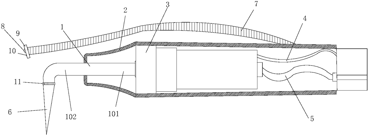
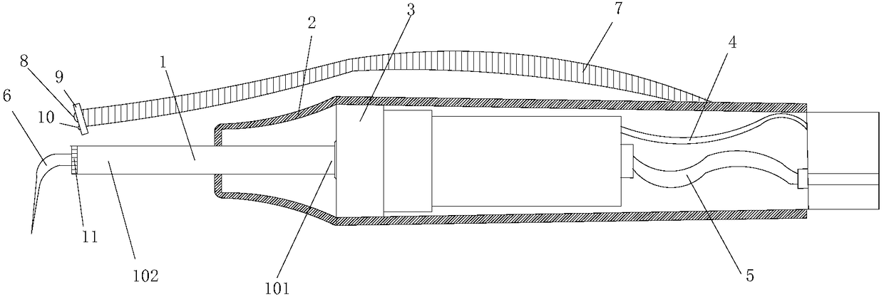
[0052] like Figure 1 to Figure 2 As shown, an ultrasonic dental scaler described in this embodiment that does not damage teeth includes a handle housing 2 and a transducer 3 disposed in the handle housing 2, and the front end of the transducer 3 is fixedly connected to the horn. The first end 101 and the second end 102 of the horn extend out of the handle shell 2; the second end 102 of the horn is connected to a pair of working tips 6 for cleaning teeth.

[0053] In this embodiment, the ultrasonic tooth scaler uses ultrasonic tooth cleaning technology to perform tooth cleaning. like figure 1 As shown in , the tooth cleaning handle of the present invention also includes electric wires 4 and water pipes 5, and the high-frequency and high-energy vibrations generated by ultrasonic waves are used to crush the calculus and stains on the tooth surface through the smooth working tip. Same as the prior art, in this embodiment, the working tip 6 is provided with a water outlet to gen...

Embodiment 2

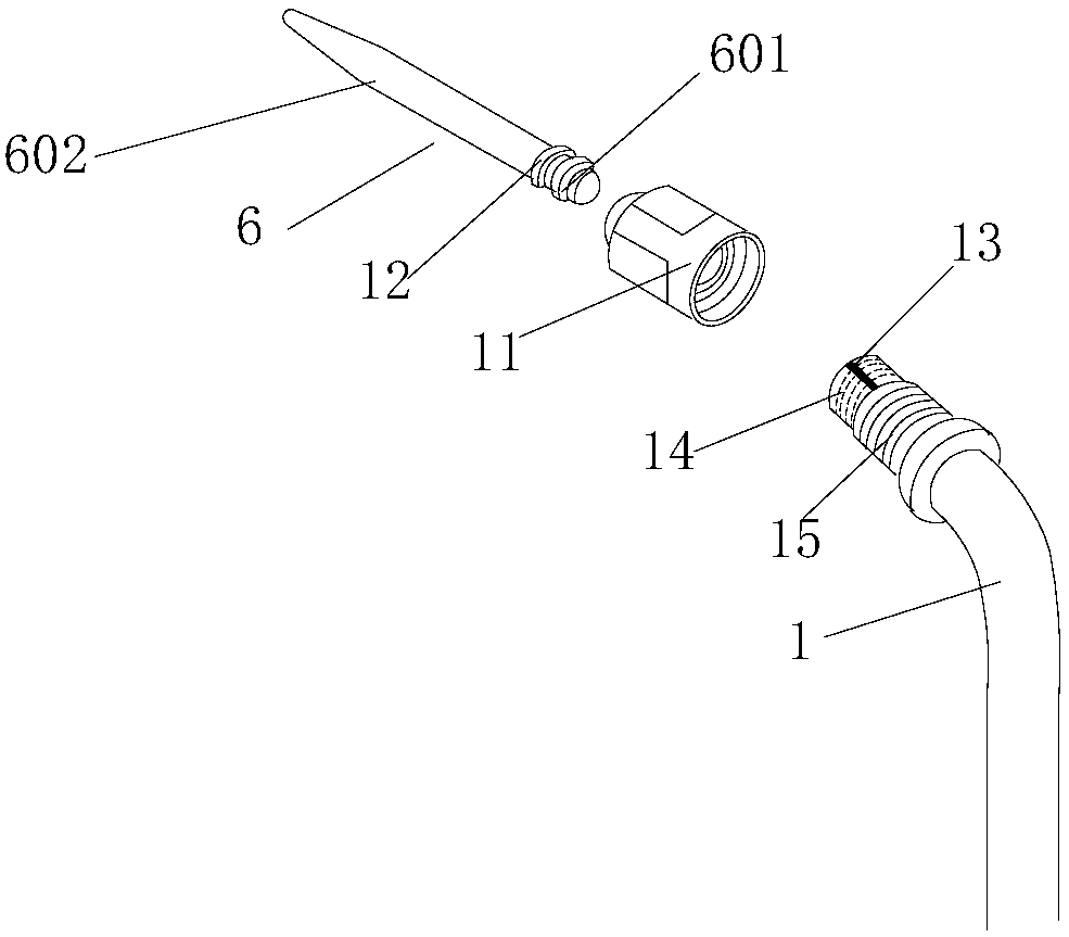
[0072] This embodiment serves as a supplement to the realization of the limiting device in the first embodiment: the positioning ring in the limiting device is a snap ring that fits on the connecting end of the working tip and is used to engage with the positioning groove on the mounting hole. The snap ring is provided with an elastic recovery device (such as a snap spring), so that the positioning ring can be retracted toward the center of the connection end when it is subjected to external pressure, and returns to its original position when the external force is removed, that is, the positioning ring passes through the connection. The deformation of the end fits into the positioning groove. The position limiting function can also be realized through the elastic engagement of the snap ring and the positioning groove.

Embodiment 3

[0074] This embodiment is further supplemented as the realization of the limiting device of the above-mentioned embodiment: in order to realize the limit of the circumferential movement of the working tip 6 by the mounting hole 13 at the same time, the limiting device uses a protrusion set on the outer surface of the connecting end 601 of the working tip. Scattered positioning blocks and positioning grooves on the inner wall of the mounting hole that match the positioning blocks are used to achieve the limiting effect. The matching method and installation process of the positioning block and the positioning groove in this embodiment can be performed with reference to the above-mentioned embodiments.


PUM


Abstract

The invention discloses an ultrasonic dental unit without tooth damage. The ultrasonic dental unit without tooth damage comprises a handle case and an energy converter arranged in the case, wherein the front end of the energy converter is fixedly connected with the first end of an amplitude change rod; the second end of the amplitude change rod extends to a position outside the case; the second end of the amplitude change rod is connected with a work point for cleaning teeth; the work point at least comprises a first work body and a second work body; the first work body and the second work body are integrally shaped or fixedly connected into a whole to form the work point with regions with different hardness. The ultrasonic dental unit also comprises an image collecting device, wherein theimage collecting device is connected with the tooth cleaning handle through a shape-changeable connecting device. Through the structural design of the amplitude change rod, the design of the work point, and the improvement of an image pick-up device and connection device, the safety and the comfort degree of the tooth cleaning equipment are integrally improved, so that the tooth cleaning handle can be more easily operated and used by an ordinary user; the healthy tooth caring mode of tooth cleaning can be completed in a self-help way at home.

Description

technical field [0001] The invention belongs to the field of medical dental cleaning instruments, and in particular relates to an ultrasonic tooth cleaning machine which does not damage teeth. Background technique [0002] The dental scaler is a special equipment for cleaning teeth, and it is a dental cleaning appliance used to remove dental calculus, smoke spots, bacterial plaque, etc. The ultrasonic scaler uses the high-frequency, high-energy vibration generated by ultrasonic waves to crush and fall off the calculus and stains on the surface of the teeth through the smooth working head on the handle of the ultrasonic scaler. Ultrasonic scalers generally include a power supply, a host, a handle and a foot switch. An ultrasonic generator is installed in the host, the working head is installed on the horn at the front end of the handle, and an ultrasonic wave connected to the ultrasonic generator through a cable is installed in the handle. Transducer, the ultrasonic transduc...

Claims


Application Information

Patent Timeline
Patent Type & Authority Applications(China)
IPC IPC(8): A61C17/20
CPCA61C17/20
Inventor 张雨同张海钟
Owner 张雨同
Why Eureka
Try Eureka