
A synchronous pressure roller filter bed device

A pressure roller and filter bed technology, applied in the field of synchronous pressure roller type filter bed devices, can solve the problems of insufficient rolling steel output, folds at the edge of the filter paper, pollution, etc. The effect of production costs

Active Publication Date: 2021-02-19
宝钢股份黄石涂镀板有限公司
View PDF10 Cites 0 Cited by
  • Summary
  • Abstract
  • Description
  • Claims
  • Application Information

AI Technical Summary

Problems solved by technology

The existing filter flat bed structure mainly includes a frame on which a box is arranged. The upper part of the box is provided with a chain bed. The inner cavity of the box below the chain bed is a clean liquid storage chamber. Pipe, fan and chain bed driving device, the upper end of the outer wall of the box is provided with an overflow pipe, and the lower end is provided with a clean liquid pipe. One side of the box is equipped with a filter paper bracket and a filter paper roll. The filter paper is laid along the surface of the chain bed. The blank-holding force of the sealing rubber is inconsistent, resulting in uneven friction between the filter paper and the sealing rubber on both sides, and the edge of the filter paper will shrink toward the middle due to the heavy pressure of the dirty liquid during the filtration process, causing wrinkles on the edge of the filter paper A large number of particles in the dirty emulsion enter the clean liquid storage chamber below the filter paper without filtering from the folds of the filter paper to pollute the clean lubricating liquid, causing roll marks to form on the surface of the strip steel; The liquid level cannot be effectively established above the filter paper, and the filter paper cannot be fed automatically normally, resulting in poor filtering effect of the filter paper. Therefore, the roll printing is replaced three times a day, which seriously restricts the surface quality of the rolled hard coil of the rolling mill, and the rolling steel output cannot be fully realized. At the same time, it also makes the roll consumption remain high

Method used


Image

  • A synchronous pressure roller filter bed device
  • A synchronous pressure roller filter bed device
  • A synchronous pressure roller filter bed device

Examples


Embodiment Construction

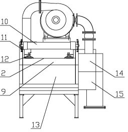
[0015] The present invention is a synchronous pressure roller filter bed device, which has a frame 1, a box body 4 is arranged on the frame body, a chain bed 9 is arranged on the upper part of the box body, and the inner cavity of the box below the chain bed is a clean liquid storage cavity 13, The top of the box is provided with a dirty liquid delivery pipe 5, a fan 6 and a chain bed driving device, the upper and lower parts of the outer wall of the box are respectively provided with an overflow pipe 14 and a clean liquid pipe 15, and the front end of the box is provided with a filter paper holder 3, The filter paper bracket is equipped with filter paper 2, and the filter paper is laid along the upper surface of the chain bed. A sealing edge holding device 12 is provided on the inner wall of the box at the edges of both sides of the filter paper, and a liquid level is also set above the sealing edge holding device on the inner wall of the box. Detection device, the rear end of...


PUM


Abstract

The invention relates to a synchronous pressure roller filter bed device, which has a frame on which a box body is arranged, a chain bed is arranged on the upper part of the box body, and a dirty liquid delivery pipe, a fan and a chain bed driving device are arranged on the top of the box body. The upper and lower parts of the outer wall of the box body are respectively provided with an overflow pipe and a clean liquid pipe. The front end of the box body is provided with a filter paper bracket, and the filter paper bracket is equipped with filter paper. The filter paper is laid along the upper surface of the chain bed. Each side edge is equipped with a sealing edge-holding device, and the rear end of the box is provided with a filter paper exporting roller, and a filter paper synchronous pressing roller device is installed above the filter paper exporting roller at the filter paper outlet on the frame, and the filter paper synchronous pressing roller device includes a symmetrical The pressure roller adjustment device and two synchronous pressure rollers installed on the frame; the invention can indirectly reduce fuel consumption, realize mutual conversion between thick filter paper and thin filter paper without wrinkling filter paper, and reduce production cost, repair, maintenance, The adjustment is simple and convenient, and the equipment is durable.

Description

technical field [0001] The invention relates to the technical field of cold rolling machinery and equipment, in particular to a synchronous pressure roller filter bed device. Background technique [0002] As one of the main units in the steel rolling production process, the cold rolling unit is equipped with an emulsion system outside the rolling mill production line according to the production process requirements. Due to the needs of production cooling and lubrication, it is divided into a clean liquid system and a dirty liquid system. To ensure the stable operation of the rolling mill equipment, the requirements for the dirty liquid system are very strict; in the existing dirty liquid system, the dirty liquid pump pumps the cooled lubricating liquid to the filter flat bed, where it is filtered through the flat bed filter paper. When it is full of dirt and cannot be filtered, when the liquid level detector above the filter paper detects that the liquid level is too high, t...

Claims


Application Information

Patent Timeline
Patent Type & Authority Patents(China)
IPC IPC(8): B01D29/09B01D29/96
CPCB01D29/096B01D29/96
Inventor 黄先武
Owner 宝钢股份黄石涂镀板有限公司
Learn More