A flow-guiding support grid for reactor catalyst bed and fluidized bed reactor
A catalyst bed and support grid technology, which is applied to chemical instruments and methods, chemical/physical processes, etc., can solve problems such as catalyst leakage, rupture, and screen deformation, so as to reduce frictional resistance, improve service life, Mitigates the effect of erosion corrosion
- Summary
- Abstract
- Description
- Claims
- Application Information
AI Technical Summary
Problems solved by technology
Method used
Image


Examples
Embodiment 1
[0062]This example is intended to illustrate a flow-flow support grill of the present invention.
[0063]The guiding flow support grid is a double-layer cylindrical structure, such asimage 3 withFigure 5 As shown, it includes a distribution cartridge 1-1, a support strip 1-2, a support strip 1-2, a contact ring plate 1-6, and an end, a connecting ring plate 1-6, and a contact 1-6, and a contactor 1-1. -3 parallel setting, the support strip 1-2 is located between the distribution cartridges 1-1 and the contactors 1-3, the contactor 1-3 adjacent to the catalyst bed 3,
[0064]The contactor 1-3 is provided with a uniformly distributed multi-ring passage hole 1-7, and is provided with a guide plate over the side surface of the catalyst bed 3 adjacent to the catalyst bed 3. 1-4, the guiding plate 1-4 is a circular shaped shaped structure, and its convex surface direct contacts the catalyst bed 3, and the concave surface towards the contactor 1-3, adjacent two-layer guide plate 1-4. There are m...
Embodiment 2
[0070]This example is intended to illustrate a flow-flow support grill of the present invention.
[0071]The guiding flow support grid is a double-layer cylindrical structure, such asFigure 4 withFigure 6 As shown, it includes a distribution cartridge 1-1, a support strip 1-2, a support strip 1-2, a contact ring plate 1-6, and an end, a connecting ring plate 1-6, and a contact 1-6, and a contactor 1-1. -3 parallel setting, the support strip 1-2 is located between the distribution cartridges 1-1 and the contactors 1-3, the contactor 1-3 adjacent to the catalyst bed 3,
[0072]The contactor 1-3 is provided with a uniformly distributed multi-ring passage hole 1-7, and is provided with a guide plate over the side surface of the catalyst bed 3 adjacent to the catalyst bed 3. 1-4, the guiding plate 1-4 is a circular shaped shaped structure, and its convex surface direct contacts the catalyst bed 3, and the concave surface towards the contactor 1-3, adjacent two-layer guide plate 1-4. There are ...
Embodiment 3
[0078]This example is used to illustrate the flow bed reactor of the present invention.
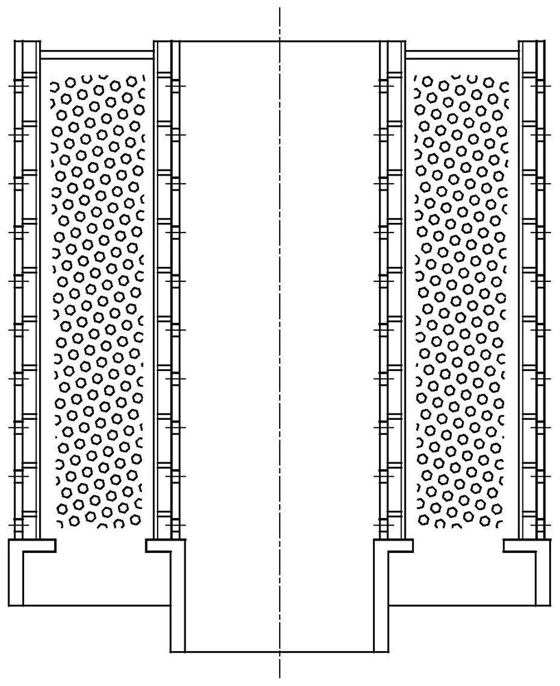
[0079]Such asFigure 12 withFigure 13 As shown, the flow bed reactor includes inner tube grid 1, an outer cylinder grid 2, a housing 4, an inlet tube 6, a gas distributor 7, an outlet tube 5, a catalyst feed tube 9, and a catalyst discharge tube 10.
[0080]The housing 4, the outer cylinder 2 and the inner cylindrical grid 1 are sequentially arranged in radial direction, and the inner tube grid is provided through the inner side wall of the housing 4 and / or bottom. 1 and the outer cylinder grid 2 is supported, the inlet tube 6 is disposed at the bottom of the housing 4, the gas distributor 7 is located above the inlet tube 6, and its axis and the inner tube grill are located. 1. The outer cylinder 2 and the axis of the housing 4 are coincident, the outlet tube 5 is disposed at the top or side of the housing 4, the catalyst bed 3 disposed in the inner tube grid 1 and outside Between the catalyst feed...
PUM
 Abstract
Description
Claims
Application Information
 - R&D
- Intellectual Property
- Life Sciences
- Materials
- Tech Scout
- Unparalleled Data Quality
- Higher Quality Content
- 60% Fewer Hallucinations
Browse by: Latest US Patents, China's latest patents, Technical Efficacy Thesaurus, Application Domain, Technology Topic, Popular Technical Reports.
© 2025 PatSnap. All rights reserved.Legal|Privacy policy|Modern Slavery Act Transparency Statement|Sitemap|About US| Contact US: help@patsnap.com