[0019] All features disclosed in this specification, or steps in all methods or processes disclosed, may be combined in any manner, except for mutually exclusive features and/or steps.
[0020] Any feature disclosed in this specification (including any appended claims, abstract and drawings), unless expressly stated otherwise, may be replaced by alternative features which are equivalent or serve a similar purpose. That is, unless expressly stated otherwise, each feature is one example only of a series of equivalent or similar features.
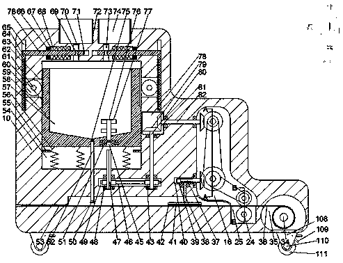
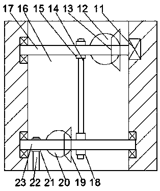
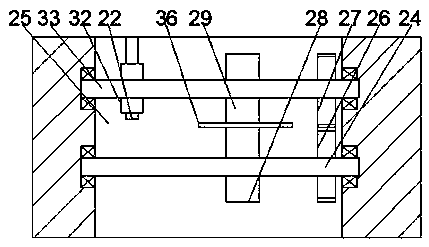
[0021] like Figure 1-Figure 3As shown, an intelligent functional textile of the device of the present invention and its manufacturing method include a body 10, a first cavity 16 is arranged in the body 10, and a second cavity 16 is arranged on the inner bottom wall of the first cavity 16. Cavity 25, the inner wall of the rear side of the first cavity 16 is provided with a motor 11, and the motor 11 is power-connected with a driving shaft 17, and the driving shaft 17 is provided with a first bevel gear 13, and on the driving shaft 17 A first pulley 15 is provided, a third cavity 78 is provided at the left end of the first cavity, and a first rotating shaft is rotatably provided between the third cavity 78 and the first cavity 16 82, the first rotating shaft 82 is provided with a second bevel gear 12 meshing with the first bevel gear 13, and the first rotating shaft 82 is provided with a third bevel gear located in the third cavity 78 81, the front and rear inner walls of the first cavity 16 are rotatably provided with a second rotating shaft 23, and the second rotating shaft 23 is provided with a second pulley 18, and the second pulley 18 is connected to the first belt A first belt 14 is provided for transmission cooperation between the wheels 15, a fourth bevel gear 19 is provided on the second rotating shaft 23, a third pulley 21 is provided on the second rotating shaft 23, and the first cavity 16 The left end is provided with a fourth cavity 40, and a worm 37 is rotatably provided between the fourth cavity 40 and the first cavity 16, and the worm 37 is provided with the fourth bevel gear. 19 meshing fifth bevel gear 20, the front and rear inner walls of the first cavity 16 are rotatably provided with a third shaft 33, the third shaft 33 is provided with a fourth pulley 32, and the fourth pulley 32 A second belt 22 is provided for transmission cooperation with the third pulley 21, a first friction wheel 29 and a first gear 27 are provided on the third rotating shaft 33, and the front and rear inner walls of the second cavity 25 are rotatable The fourth rotating shaft 24 is provided with the second gear 26 meshing with the first gear 27, and the fourth rotating shaft 24 is provided with a friction wheel 29 opposite to the first friction wheel 29. The second friction wheel 28, the fifth cavity 49 is arranged below the third cavity 78, and the fifth rotating shaft 80 is rotatably arranged between the third cavity 78 and the fifth cavity 49, so that The fifth rotating shaft 80 is provided with a sixth bevel gear 79 meshing with the third bevel gear 81, and the fifth rotating shaft 80 is provided with a third gear 43 located in the fifth cavity 49. An installation cavity 54 is provided above the fifth cavity 49, and a spline shaft 47 is rotatably provided between the installation cavity 54 and the fifth cavity 49, and a spline shaft 47 located on the first The fourth gear 48 in the five-cavity 45, a chain 46 is provided for transmission cooperation between the fourth gear 48 and the third gear 43, and a sliding barrel 58 is slidably installed in the installation cavity 54, and the sliding barrel 58, the bottom end surface is rotatably provided with a spline sleeve 51, the spline sleeve 51 is provided with a spline groove 45 opposite to the spline shaft 47, and the bottom end surface of the body 10 is provided with a moving device, including a roller seat 108 And brake pad 109.
[0022] Beneficially or exemplary, wherein, the sliding barrel 58 is provided with a stirring chamber 57, and the top end surface of the spline sleeve 51 is provided with a rotating shaft 76, and the rotating shaft 76 extends upward into the stirring chamber 57, The rotating shaft 76 is provided with a plurality of sets of rotating arms 77, the inner bottom wall of the stirring chamber 57 is provided with a discharge pipe 52, and a first solenoid valve 75 is arranged in the discharge pipe 52, and the installation chamber 54 is left and right The inner wall is respectively provided with a first limit block 55, a return spring 56 is provided between the sliding barrel 58 and the bottom wall of the installation cavity 54, and a first rack 60 is respectively provided on the left and right end surfaces of the sliding barrel 58, so that The left and right ends of the installation chamber 54 are respectively provided with a rotating chamber 62, and the left side of the rotating chamber is provided with a first chute 65, and a first slide bar 64 is slidably installed in the first chute 65, and the first slide bar 64 is provided with a second rack 63 on the right end surface, and the front and rear inner walls of the rotating cavity 62 are rotatably provided with a sixth rotating shaft 61, and the sixth rotating shaft 61 is provided with the second rack 63 and the second rack 63. A rack 60 meshes with the fifth gear 59 .
[0023] Beneficially or exemplarily, wherein, the top end surface of the machine body 10 is symmetrically provided with an open raw material box 72, and a raw material chamber 74 is arranged inside the raw material box 72, and the gap between the raw material chamber 74 and the installation chamber 54 is A blanking cavity 73 is provided, and a second electromagnetic valve 70 is arranged in the blanking cavity 73. The left and right inner walls of the blanking cavity 73 are respectively provided with second chute 71, and the second chute 71 is slidably installed with The second slide bar 85 is provided with a through hole 69 opposite to the blanking cavity 73 inside the second slide bar 85, and the upper and lower inner walls of the second chute 71 are provided with a limit groove 67, and the limit groove 67 A second limiting block 66 fixedly connected to the second sliding rod 85 is arranged inside, and a pressing spring 68 is arranged between the second limiting block 66 and the inner wall of the limiting groove 67 .
[0024] Beneficially or exemplary, wherein, a movable chamber 53 is provided below the fourth cavity 40, and a seventh shaft 38 is rotatably provided between the fourth cavity 40 and the movable chamber 53, and the The seventh rotating shaft 38 is provided with a worm gear 39 meshed with the worm 37, the seventh rotating shaft 38 is provided with a turntable 41 in the movable chamber 53, and the bottom end surface of the turntable 41 is provided with a brush 42, thereby Brush the functional material evenly, the discharge pipe 52 extends downwards into the activity chamber 53 , and the end of the discharge pipe 52 is provided with a spray head 50 .
[0025] Beneficially or exemplary, wherein, the right side end of the first cavity 16 is provided with a material storage chamber 35 communicating with an external material storage tank, and a wheel hub 34 is rotatably provided in the material storage chamber 35, so Said hub 34 is wound with cloth 36.
[0026] Beneficially or exemplary, wherein, the roller seats 108 are respectively fixedly connected to the four corners of the body 10, and the eighth rotating shaft 110 is rotatably arranged in the roller seat 108, and the eighth rotating shaft 110 is fixedly connected with the roller 111, and the roller seat 108 is rotatably provided with a brake pad 109 that cooperates with the roller 111. Through the roller 111 and the brake pad 109, the movement of the device is improved. convenience.
[0027] In the initial state of the device of the present invention, the spline shaft 47 is not in contact with the spline sleeve 51 , and the through hole 69 communicates with the blanking cavity 73 .
[0028] Start working, add required raw material in described raw material cavity 74, add constantly, at this moment described sliding bucket 58 moves downwards, drives described second slide bar 85 to move to the right, to described through hole 69 and described The blanking cavity 73 is dislocated, and now the spline shaft 47 is splined with the spline sleeve 51, and the motor 11 is turned on to drive the driving shaft 17 to rotate, and the rotation of the driving shaft 17 will drive the The first pulley 15 and the first bevel gear 13 rotate, the rotation of the first bevel gear 13 will drive the rotation of the second bevel gear 12, and the rotation of the second bevel gear 12 will drive the sixth bevel gear 79 rotation, the rotation of the sixth bevel gear 79 will drive the rotation of the fifth shaft 80, the rotation of the fifth shaft 80 will drive the rotation of the spline shaft 47, and the rotation of the spline shaft 47 will drive the rotation of the spline shaft 47. Key sleeve 51 rotates, and will drive described rotating shaft 76 to rotate simultaneously, starts to stir, and at the same time, described first pulley 15 rotates and will drive described second rotating shaft 23 to rotate, and described second rotating shaft 23 rotates will drive all The fifth bevel gear 20 and the third pulley 21 rotate, the fifth bevel gear 20 will drive the seventh rotating shaft 38 to rotate, the seventh rotating shaft 38 will drive the turntable 41 to rotate, and at the same time The rotation of the third pulley 21 will drive the rotation of the fourth pulley 32, the rotation of the fourth pulley 32 will drive the rotation of the third shaft 33, and the rotation of the third shaft 33 will drive the rotation of the fourth shaft 24 Rotate, will drive friction wheel to rotate simultaneously, described cloth 36 is flattened, and at the same time, described first electromagnetic valve 75 is opened. The mixed raw material will be sprinkled on the cloth 36 through the nozzle, and at the same time, the turntable 41 will spread the mixed raw material evenly. When the raw material in the stirring chamber 57 is reduced to a certain extent, the spline shaft 47 and the spline The sleeve 51 is disengaged, the first electromagnetic valve 75 is closed, and then raw materials are added into the stirring chamber 57, and the actions in between will be repeated.
[0029] The beneficial effects of the present invention are:
[0030] Start to work, add the required raw materials into the raw material cavity, and keep adding, at this time, the sliding barrel moves downward, driving the second sliding bar to move to the right, until the through hole is misaligned with the blanking cavity , at this time, the splined shaft is splined with the splined sleeve, and the motor is turned on, which will drive the active shaft to rotate, and the rotation of the active shaft will drive the first pulley and the first cone gear rotation, the rotation of the first bevel gear will drive the rotation of the second bevel gear, the rotation of the second bevel gear will drive the rotation of the sixth bevel gear, and the rotation of the sixth bevel gear will drive the rotation of the fifth bevel gear The rotation of the rotating shaft, the rotation of the fifth rotating shaft will drive the rotation of the spline shaft, the rotation of the spline shaft will drive the rotation of the spline sleeve, and at the same time will drive the rotation of the rotation shaft to start stirring. At the same time, the The rotation of the first pulley will drive the rotation of the second shaft, the rotation of the second shaft will drive the rotation of the fifth bevel gear and the third pulley, and the rotation of the fifth bevel gear will drive the rotation of the first The seven rotating shafts rotate, the rotation of the seventh rotating shaft will drive the turntable to rotate, and the rotation of the third pulley will drive the rotation of the fourth pulley, and the rotation of the fourth pulley will drive the rotation of the third rotating shaft , the third rotating shaft drives the fourth rotating shaft to rotate, and at the same time drives the friction wheel to rotate to flatten the cloth, and at the same time, the first electromagnetic valve is opened. The mixed raw materials will be sprinkled on the cloth through the nozzle, and at the same time, the turntable will spread the mixed raw materials evenly. The first electromagnetic valve is closed, and then the raw materials are added into the stirring chamber, and the actions in between will be repeated;
[0031] The device of the present invention has a simple structure and is easy to operate, does not need to use manpower for stirring, greatly improves the stirring efficiency, and greatly saves labor costs, greatly speeds up the cloth processing time, and integrates the stirring and dyeing of cloth, which is extremely It greatly improves the quality of functional textiles, greatly reduces the overall cost, increases income, and accelerates the degree of automation in the factory, making management more convenient and greatly reducing the outflow of unqualified products.
[0032] The basic principles, main features and advantages of the present invention have been shown and described above. Those skilled in the art should understand that the present invention is not limited by the above-mentioned embodiments, and what are described in the above-mentioned embodiments and description are only the principle of the present invention, and without departing from the spirit and scope of the present invention, the present invention will also have various Variations and improvements all fall within the claimed invention. The protection scope of the present invention is defined by the appended claims and their equivalents.