
Electromagnetic forming device and method for providing continuous electromagnetic force

A technology of electromagnetic forming and electromagnetic force, which is applied in the field of material processing, can solve the problems of slow increase of electromagnetic force, low forming efficiency, and influence on forming accuracy, and achieve the effect of increasing pulse current time, realizing flexible manufacturing, and improving forming efficiency

Active Publication Date: 2018-11-23
CENT SOUTH UNIV
View PDF6 Cites 9 Cited by
  • Summary
  • Abstract
  • Description
  • Claims
  • Application Information

AI Technical Summary

Problems solved by technology

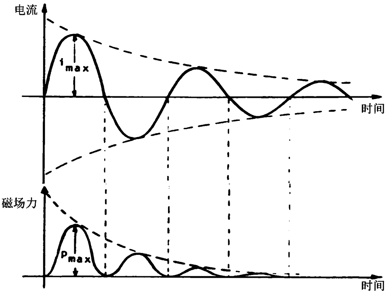
This pulse electromagnetic force has the following two problems: (1) The pulse electromagnetic force mainly acts on the deformation of the material in the first half wave, and the other half waves can be ignored due to the large attenuation of the electromagnetic force, so the magnetic field force acts for a short time and the forming efficiency is low ; (2) The pulse current increases from the initial value of 0, causing the electromagnetic force to increase slowly
However, multiple discharges and multiple sets of coil structures required to improve precision will weaken the forming efficiency
And for high-hardness materials, the high-speed collision between the material and the mold driven by magnetic field force still cannot solve the problem of rebound after high-speed collision, which will eventually affect the forming accuracy

Method used


Image

  • Electromagnetic forming device and method for providing continuous electromagnetic force
  • Electromagnetic forming device and method for providing continuous electromagnetic force
  • Electromagnetic forming device and method for providing continuous electromagnetic force

Examples


Embodiment 1

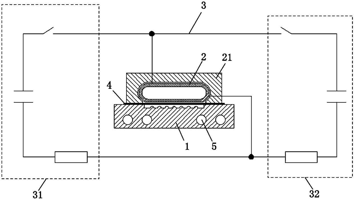
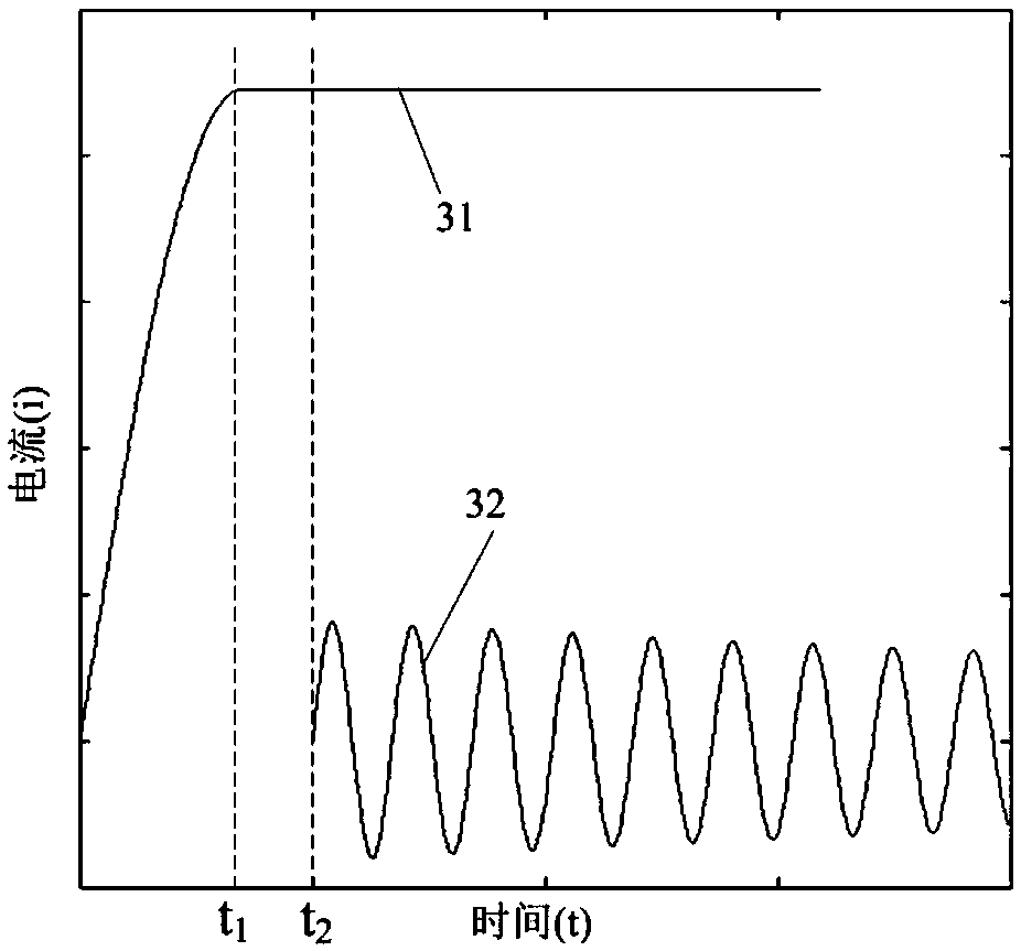
[0039] Such as Figure 1 to Figure 5 As shown, the electromagnetic forming device providing continuous electromagnetic force in this embodiment includes a die 1, a coil 2 and a discharge circuit 3, the coil 2 is arranged on the die 1, and the sheet material 4 to be formed is arranged on the die 1 and the coil 2, the coil 2 is electrically connected to the discharge circuit 3, and the discharge circuit 3 includes a steady-state magnetic field discharge circuit 31 capable of generating a steady-state magnetic field and an alternating magnetic field discharge circuit 32 capable of generating an alternating magnetic field, the steady-state magnetic field discharge circuit 31 and The alternating magnetic field discharge circuits 32 are electrically connected to the coils 2 respectively. The steady-state magnetic field discharge circuit 31 can generate a large value of steady-state current to determine the size of the magnetic field, and the alternating magnetic field discharge circ...

Embodiment 2

[0047] The electromagnetic forming device providing continuous electromagnetic force of this embodiment is basically the same as that of Embodiment 1, the main difference is that, as Figure 6 and Figure 7 As shown, the bottom surface of the cavity 11 in this embodiment is a concave fine structure. The sheet material 4 is deformed under the action of the magnetic field force, and is attached to the bottom surface of the cavity 11 of the die 1 to obtain the sheet material 4 with a concave fine structure.

Embodiment 3

[0049] The electromagnetic forming device providing continuous electromagnetic force of this embodiment is basically the same as that of Embodiment 1, the main difference is that, as Figure 8 and Figure 9 As shown, the bottom surface of the cavity 11 in this embodiment is a planar structure without protrusions and indentations. The sheet material 4 is deformed under the action of the magnetic field force, and is attached to the bottom surface of the cavity 11 of the die 1 to obtain the sheet material 4 with a planar structure.


PUM


Abstract

The invention discloses an electromagnetic forming device for providing continuous electromagnetic force. The electromagnetic forming device for providing the continuous electromagnetic force comprises a concave die, a coil and a discharging loop. The coil is arranged on the concave die, a sheet to be formed is arranged between the concave die and the coil, the coil is electrically connected withthe discharging loop, the discharging loop comprises a steady-state magnetic field discharging loop capable of generating a steady-state magnetic field and an alternating magnetic field discharging loop capable of generating an alternating magnetic field, and the steady-state magnetic field discharging loop and the alternating magnetic field discharging loop are electrically connected with the coil separately. The invention further discloses an electromagnetic forming method. The electromagnetic forming method comprises the steps of discharging of the steady-state magnetic field discharging loop, discharging of the alternating magnetic field discharging loop, superimposing of the current generated by the steady-state magnetic field discharging loop and the current generated by the alternating magnetic field discharging loop, obtaining induced eddy current by induction of alternating pulse current, forming completing of the sheet under the action of magnetic field force and the like. The electromagnetic forming device for providing the continuous electromagnetic force has the advantages of being high in forming efficiency and good in forming precision, effectively avoiding sheet rebound, being capable of providing the continuous electromagnetic force, accurately regulating and controlling the electromagnetic force to realize flexible manufacturing and the like.

Description

technical field [0001] The invention belongs to the field of material processing, and in particular relates to an electromagnetic forming device and method for providing continuous electromagnetic force. Background technique [0002] The traditional "electromagnetic forming" technology, also called "electromagnetic pulse forming" technology, is a method of high-speed machining of metal workpieces using pulsed electromagnetic force. In the traditional electromagnetic pulse shaping process, capacitors, coils, and discharge circuits constitute an RLC circuit. Energy is stored in the capacitor, and when the discharge switch is closed momentarily, a decaying alternating current will flow through the coil. This alternating current will get an induced current on the surface of the metal workpiece opposite to the direction of the coil current, thereby generating a pulsed electromagnetic force on the workpiece, see figure 1 (For details, see the literature "some measurements of the...

Claims


Application Information

Patent Timeline
Patent Type & Authority Applications(China)
IPC IPC(8): B21D26/14B21D37/16
CPCB21D26/14B21D37/16
Inventor 崔晓辉张志武喻海良
Owner CENT SOUTH UNIV
Learn More