
Method, device, storage medium and computer device for planning laser cutting path

A path planning and laser cutting technology, which is applied to laser welding equipment, welding equipment, metal processing equipment, etc., can solve the problems of cutting time, irrationality, and low cutting efficiency of path planning scheme cutting path

Active Publication Date: 2018-11-23
HANS LASER TECH IND GRP CO LTD +1
View PDF5 Cites 40 Cited by
  • Summary
  • Abstract
  • Description
  • Claims
  • Application Information

AI Technical Summary

Problems solved by technology

[0004] However, the "n" type algorithm in the traditional technology is only suitable for the situation where the number of parts is small and the arrangement of parts is relatively regular. The path planning scheme may have a cutting path or a long cutting time, resulting in low cutting efficiency, which leads to unscientific and unreasonable problems in the path planning scheme

Method used

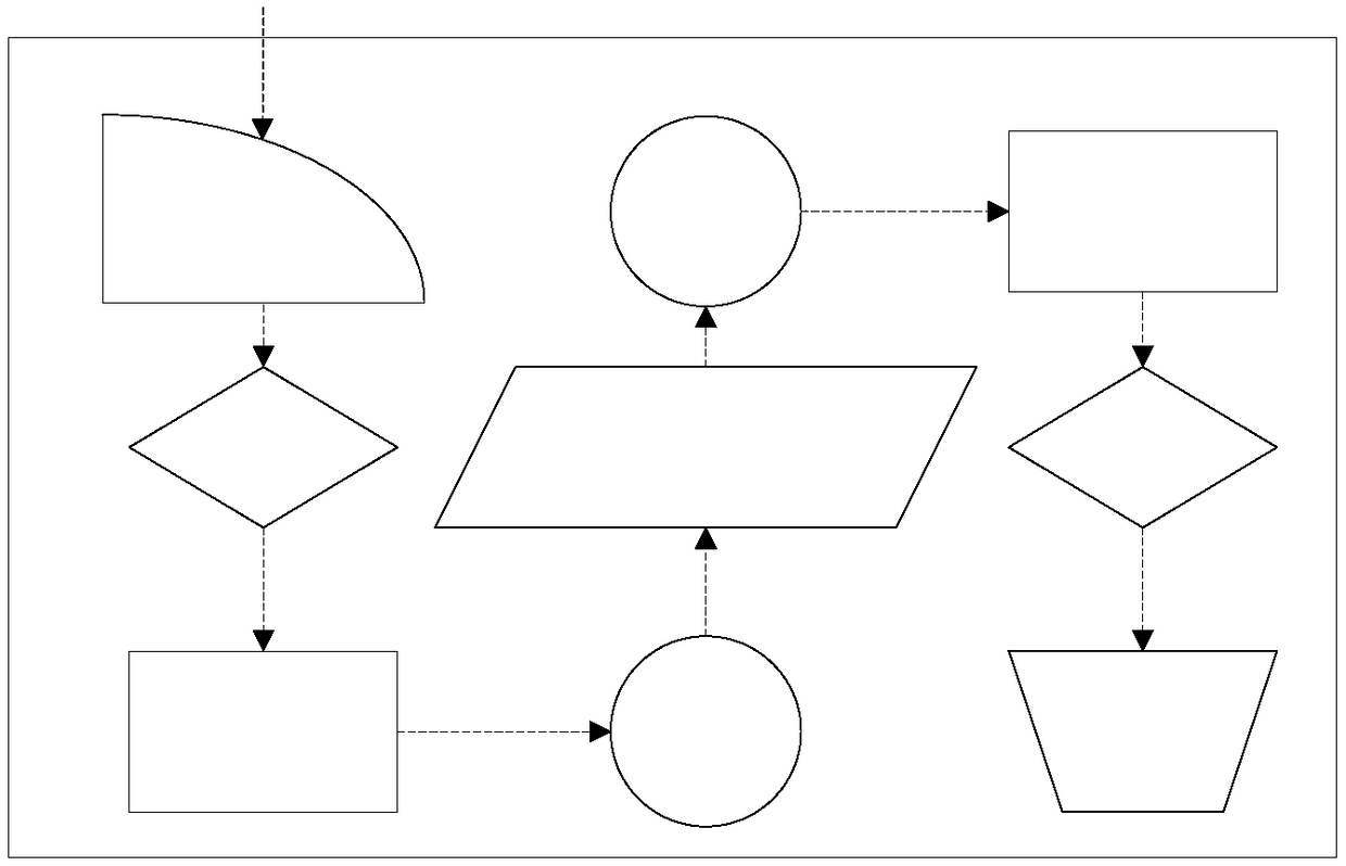

Image

  • Method, device, storage medium and computer device for planning laser cutting path
  • Method, device, storage medium and computer device for planning laser cutting path
  • Method, device, storage medium and computer device for planning laser cutting path

Examples


Embodiment Construction

[0032] Before explaining the technical solution of this application, some relevant content in the laser cutting technology will be explained first.

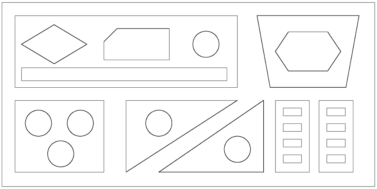
[0033] The most basic geometric unit of laser cutting graphics is the contour, which is a closed figure composed of straight lines and arcs. For any simple or complex contour, we can define the connection point between the straight line and the straight line, the connecting point between the straight line and the arc, and the connecting point between the arc and the arc as the vertices of the contour, and the straight line or arc that will constitute the contour Defined as an edge, for a circular profile, its vertices can be at any position. refer to figure 1 , typical contours include circles, polygons, special-shaped contours composed of straight lines and arcs, etc.

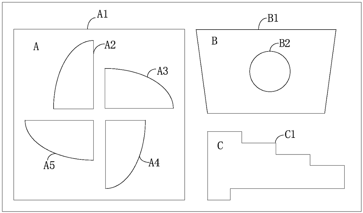
[0034] Parts are composed of contours and are the most direct output of laser cutting. Such as figure 2 As shown, a complete part to be processed contains a...


PUM


Abstract

The invention relates to a method, device, storage medium and computer device for planning a laser cutting path, wherein the part information and layout information of a part to be cut are obtained; numbering processing on the part to be cut is carried out so as to obtain a serial number combination; according to the number combination, the part information and the layout information, the information of a shortest cutting path is obtained; according to the number combination, part information and layout information corresponding to the information of the shortest cutting path, the cutting pathis planned to obtain the path planning information. By carrying out numbering and combination on the part to be cut, after calculating the length of the cutting path corresponding to each combination, a combination corresponding to the shortest path is selected as the optimal part cutting sequence and the path planning is carried out so as to ensure the integral cutting path is the shortest, so that the laser cutting time is shortened, the laser cutting efficiency is improved, and the scientificity and the rationality of the laser cutting path planning are improved.

Description

technical field [0001] The invention relates to the technical field of laser cutting, in particular to a laser cutting path planning method, device, storage medium and computer equipment. Background technique [0002] With the development of automation control technology, the application of laser cutting is becoming more and more extensive. Laser cutting refers to the use of high-power laser beams to irradiate the material to be cut, and the irradiated part of the material to be cut is heated and evaporated to form a narrow (such as about 0.1mm) slit. During the cutting process, the laser cutting operation of the material to be cut is completed by controlling the cutting path of the laser beam to control the formation position of the slit. [0003] In the laser cutting process, in order to improve cutting efficiency, laser cutting path planning is required. Traditional technology usually uses "n" type algorithm to complete path planning, with figure 1 Examples of cutting ...

Claims


Application Information

Patent Timeline
Patent Type & Authority Applications(China)
IPC IPC(8): B23K26/38B23K26/70
CPCB23K26/38B23K26/702
Inventor 封雨鑫陈焱高云峰
Owner HANS LASER TECH IND GRP CO LTD
Learn More