Plug-in grabbing fixture

A fixture and plug-in technology, applied in the field of fixtures, can solve problems such as high fixture cost and low assembly efficiency

Active Publication Date: 2020-03-10
GIGA BYTE TECH CO LTD
View PDF6 Cites 0 Cited by
  • Summary
  • Abstract
  • Description
  • Claims
  • Application Information

AI Technical Summary

Problems solved by technology

[0004] In view of the above problems, the present invention discloses a plug-in grabbing jig, which solves the problems in the prior art that each part needs to be equipped with a dedicated jig, resulting in low assembly efficiency and high jig cost.

Method used


Image

  • Plug-in grabbing fixture
  • Plug-in grabbing fixture
  • Plug-in grabbing fixture

Examples


Embodiment Construction

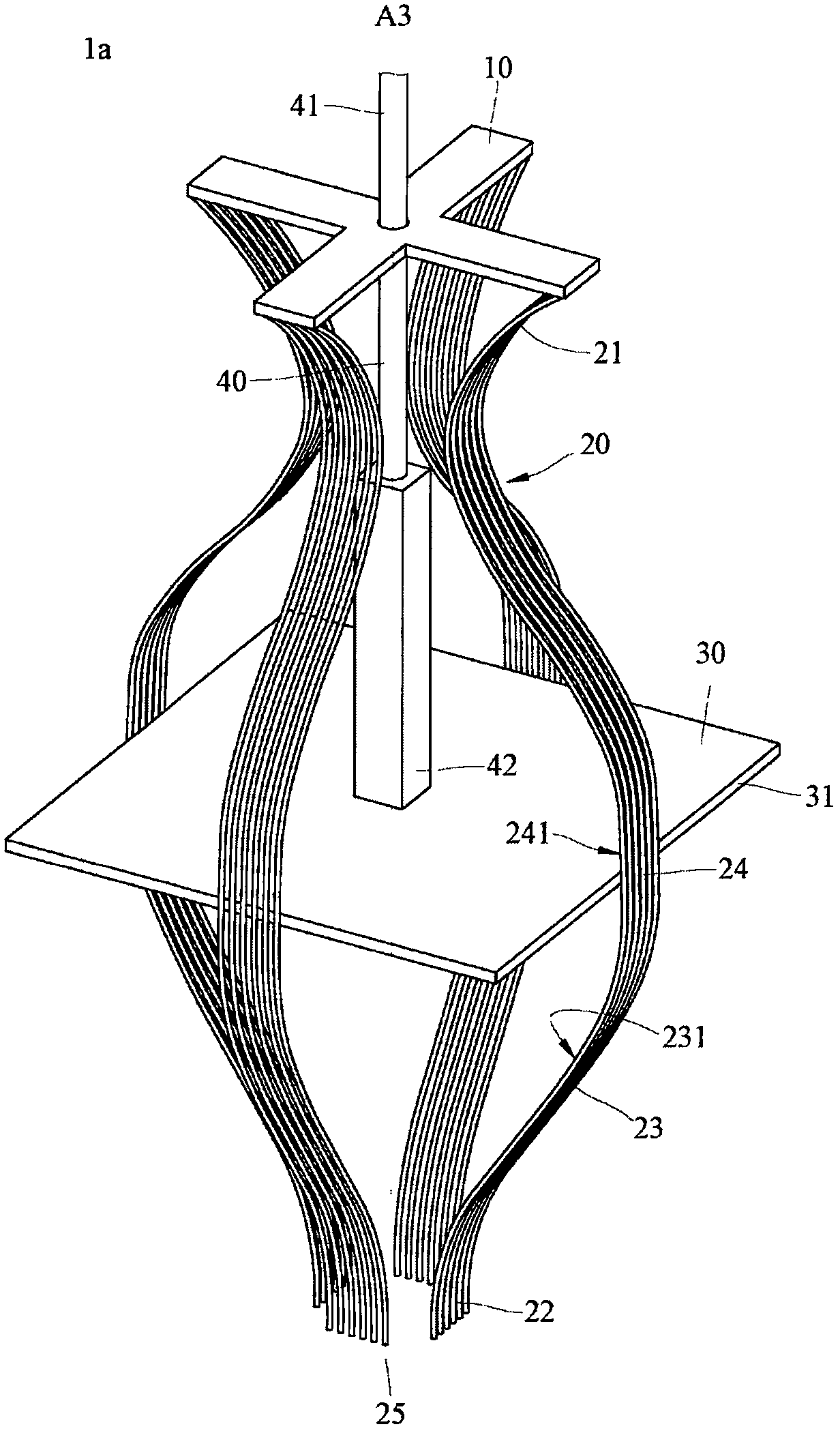
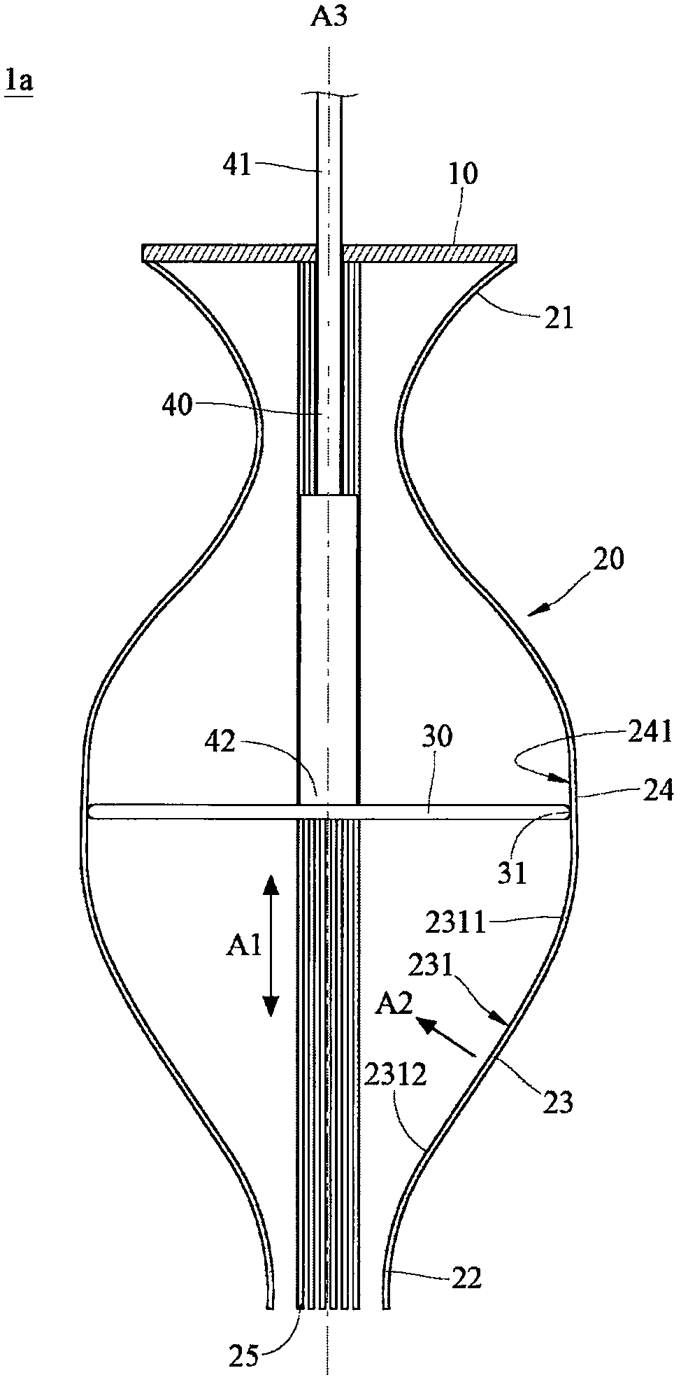
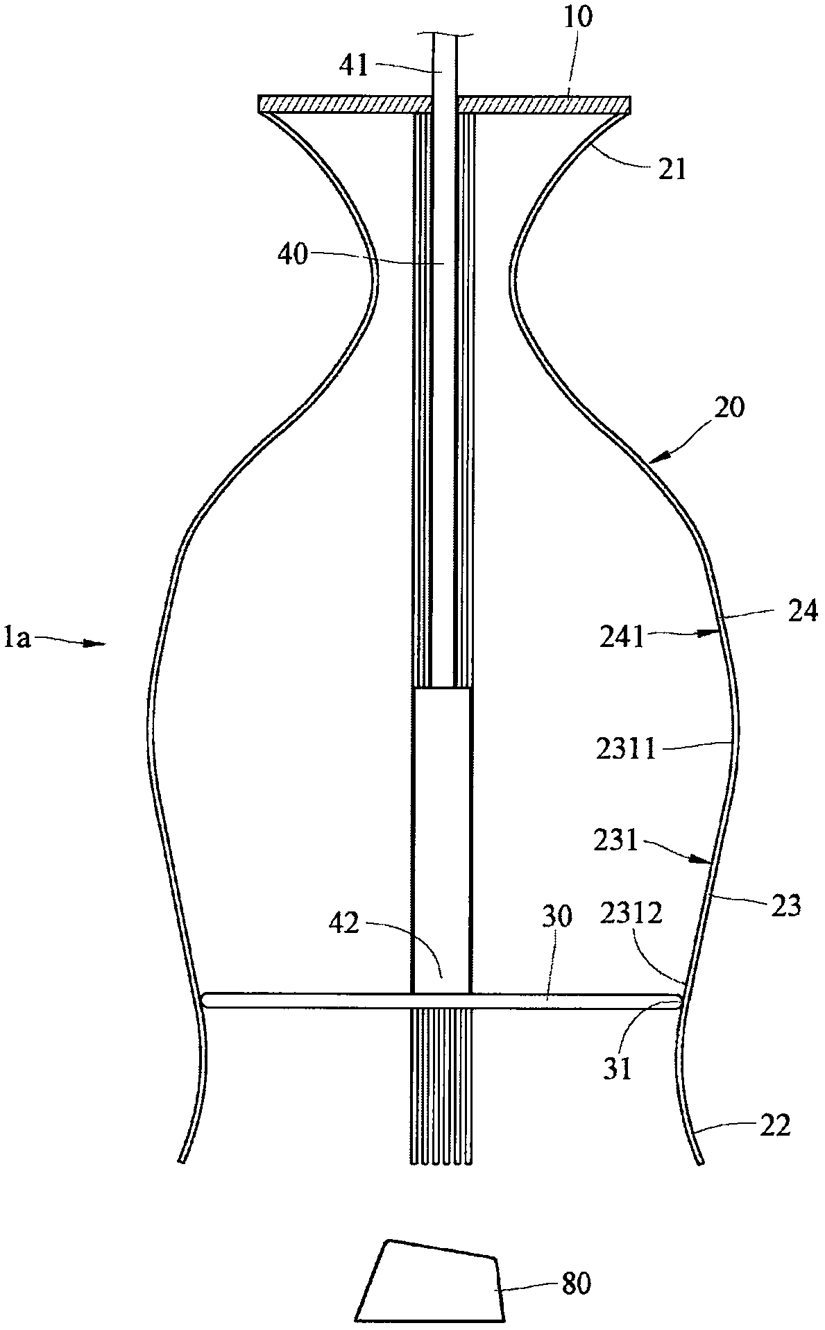
[0045] see Figure 1 to Figure 2 . figure 1 It is a three-dimensional schematic diagram of the plug-in grabbing jig according to the first embodiment of the present invention. figure 2 for figure 1 sectional schematic diagram. In this embodiment, the plug-in grabbing jig 1 a includes a fixing part 10 , a plurality of elastic parts 20 , a pushing part 30 and a connecting part. In this embodiment, the connecting part is a joystick 40 .

[0046] In this embodiment, the fixing member 10 is in the shape of a cross. But this is not taken as an example. In other embodiments, the fixing member 10 may be polygonal or circular.

[0047] Each elastic member 20 includes a connecting section 21 , a grasping section 22 , a first pushed section 23 and a second pushed section 24 . The connecting section 21 of the elastic member 20 is connected to different sides of the fixing member 10 . The gripping section 22 is opposite to the connecting section 21 . The first pushed section 23 is ...


PUM


Abstract

The invention discloses a plug-in grabbing jig. The plug-in grabbing jig comprises a fixing part, a pushing butting part, a connecting part and a plurality of elastic parts. The pushing butting part is provided with an outer edge and can be relatively close to or far away from the fixing part in the sliding direction. One end of the connecting part is connected with the fixing part, and the otherend of the connecting part is connected with the pushing butting part. The elastic parts are annularly arranged on the outer edge of the pushing butting part. Each elastic part comprises a connectingsection, a grabbing section and a first pushing section. The connecting section of each elastic part is connected with the fixing part, and the connecting sections are opposite to the grabbing sections. One sides, facing the connecting part, of first pushing sections are provided with pushing inclined surfaces, and the first pushing sections are located between the connecting sections and the grabbing sections. Acute angles are formed between the normal directions and the sliding directions of the pushing inclined surfaces. The outer edge of the pushing butting part can be pushed against the pushing inclined surfaces of the first pushing sections so as to drive the grabbing sections of the elastic parts to retract or expand outwards.

Description

technical field [0001] The invention relates to a jig, in particular to a jig for grabbing an insert. Background technique [0002] Nowadays, with the rapid development of science and technology, computer equipment has become one of the indispensable tools in people's life and work. The composition of a general personal computer mainly includes four parts: the mainframe, monitor, keyboard, and mouse. However, whether it is a host, a monitor, a keyboard or a mouse, they are not integrally formed, but assembled from various parts. [0003] Taking the mechanical switch keyboard as an example, the keys of the mechanical switch keyboard generally include a keycap, a shaft, a spring, a base, and a conductive metal sheet. Due to the small size of these parts, jigs are needed to assist in grabbing and installing during the assembly process. Because the appearance and size of keycaps, shafts, springs, bases, and conductive metal sheets are different, in order to ensure that the va...

Claims


Application Information

Patent Timeline
Patent Type & Authority Patents(China)
IPC IPC(8): B23P19/00H01H11/00
CPCB23P19/007H01H11/00
Inventor 黄顺治王晓宜廖昌斌吕景豫
Owner GIGA BYTE TECH CO LTD
Why Eureka
Try Eureka