Mold-locking head plate of injection molding machine

An injection molding machine and mold clamping technology, applied in the field of injection molding equipment, can solve the problems of increasing the amount of manufacturing template materials and processing costs, unable to solve the contradiction between template performance and manufacturing cost, affecting the dimensional accuracy of injection molding products, etc., to improve rigidity, vibration, etc. Small, rigid effect

Pending Publication Date: 2018-11-23
佛山市宝捷精密机械有限公司
View PDF0 Cites 0 Cited by
  • Summary
  • Abstract
  • Description
  • Claims
  • Application Information

AI Technical Summary

Problems solved by technology

[0002] The clamping head plate is used to fix the four clamping guide pillars and the fixed mold part of the mold. During the mold clamping process of the injection molding machine, the clamping head plate will produce relatively large elastic deformation due to the clamping force of the mold. The elasticity of the template The size of deformation is very important for injection molded products. Excessive deformation will affect the dimensional accuracy of injection molded products, and produce flash on the parting surface of plastic products, which will seriously affect the quality of products and lead to the generation of unqualified products; At the same time of deformation, each dangerous area of ​​the formwork itself will generate greater stress. The greater the deformation, the greater the stress will be. When the stress exceeds the allowable stress of the formwork material, it will cause the formwork to crack and fail, which is very serious for the injection molding machine. , will lead to huge economic losses. In the actual production process, the problem of cracking templates and product flashing is caused by excessive deformation.
[0003] In addition, in the actual production process, the sudden change in the movement speed of the second clamping plate will lead to the generation of impact force, which acts on the clamping head plate through the guide post. According to the principle of conservation of momentum, the clamping head plate will follow the clamping force. The direction of movement of the second plate makes a corresponding reverse swing, causing the whole machine to vibrate
[0004] Theoretically, the smaller the deformation and stress of the clamping head plate, the better. In the past, in order to pursue smaller deformation and stress, the method of increasing the thickness of the template was often used to reduce the deformation and stress. Increase the amount of materials and processing costs for manufacturing templates, resulting in a large waste of materials and an increase in processing and transportation costs. This method cannot solve the contradiction between the performance of templates and manufacturing costs

Method used


Image

  • Mold-locking head plate of injection molding machine
  • Mold-locking head plate of injection molding machine
  • Mold-locking head plate of injection molding machine

Examples


Embodiment Construction

[0034] The technical solutions of the present invention will be further described below in conjunction with the drawings and specific embodiments.

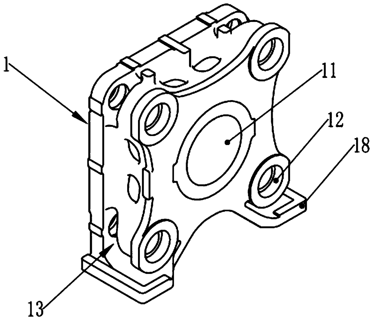
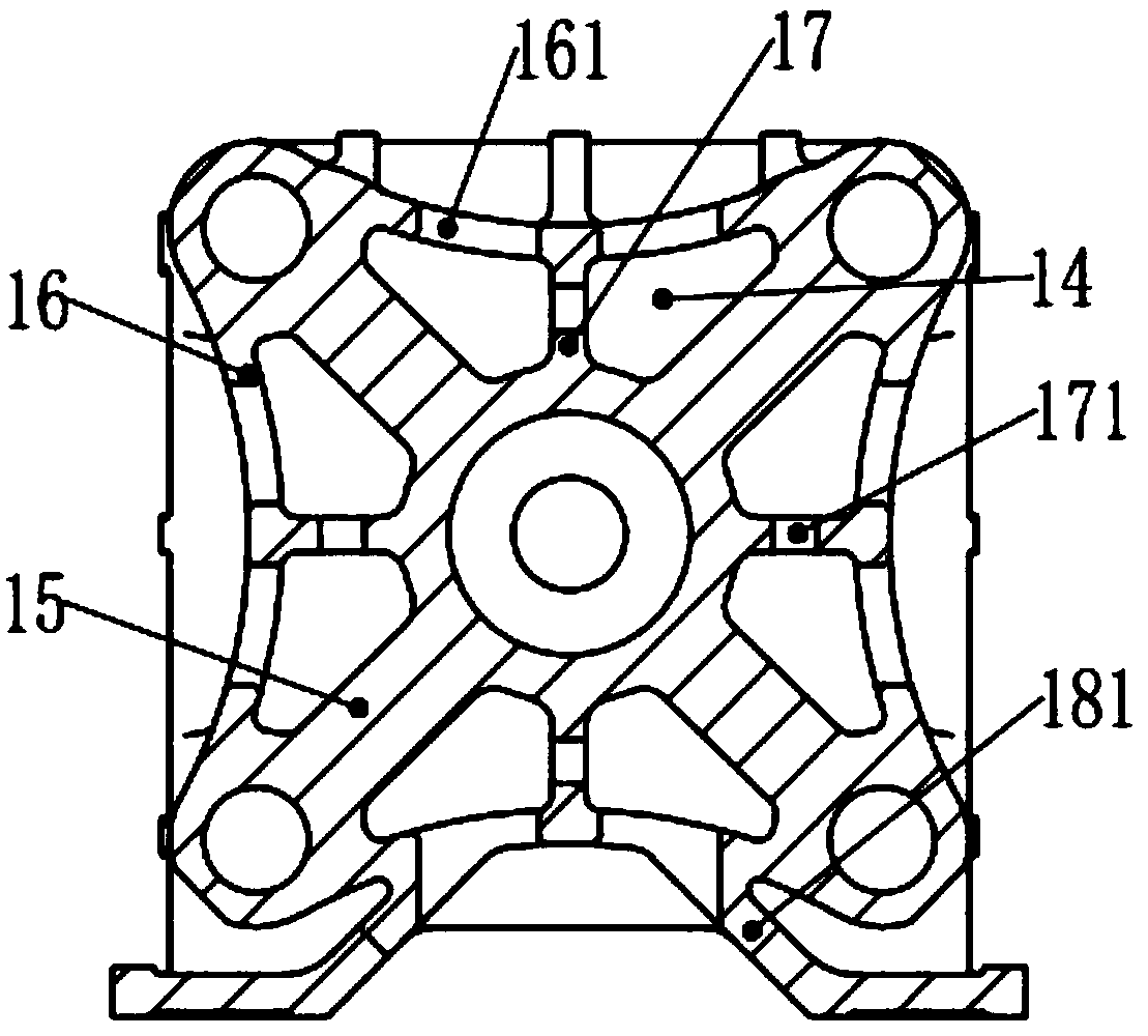
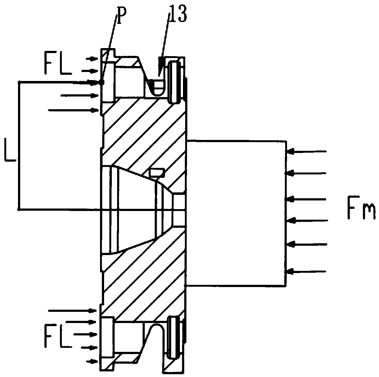
[0035] Such as Figure 1 to Figure 5 , comprising a main body 1, each of the four corners of the main body 1 is provided with a guide post mounting hole 12, each side of the four corners of the main body 1 is provided with an unloading groove 13, and the unloading groove 13 is connected with the guide post mounting hole 12 through, the unloading groove 13 is narrowed from the notch to the bottom of the groove.

[0036] The guide post installation hole 12 is used to install the guide post. During the mold clamping process, the resultant force of the four guide posts to the pulling force FL of the body 1 and the mold clamping force Fm form a group of balanced forces. When the body 1 is subjected to the mold clamping force Fm, the guide post The post installation hole 12 will receive the pulling force FL of the guide post to the bod...


PUM


Abstract

A mold-locking head plate of an injection molding machine comprises a body, guiding column mounting holes are formed in the four corners of the body correspondingly, unloading grooves are laterally formed in the four corners of the body correspondingly, the unloading grooves communicate with the guiding column mounting holes, and the unloading grooves are narrowed from groove openings to the groove bottoms. The guiding column mounting holes are used for mounting guiding columns, in the mold locking process, the surface of the body deforms towards the interiors of the unloading grooves, distribution of the tensile force of the guiding columns to the body moves towards the center of the body, action points of the tensile force moves towards the center of the body along with the change trendof stress distribution, thus the force arm from the action points of the tensile force to the center of the body is shortened, the deformation of the middle of the body is decreased, it is ensured that a whole device operates stably in the production process and is small in vibration, the using amount of materials for manufacturing of the mold-locking head plate is decreased, and the cost is lowered; and according to computer finite element analysis comparison, the deformation of the mold-locking head plate is smaller than that of a common mold plate by about 20%, and mold plate rigidity is effectively improved.

Description

technical field [0001] The invention relates to the technical field of injection molding equipment, in particular to a clamping head plate of an injection molding machine. Background technique [0002] The clamping head plate is used to fix the four clamping guide pillars and the fixed mold part of the mold. During the mold clamping process of the injection molding machine, the clamping head plate will produce relatively large elastic deformation due to the clamping force of the mold. The elasticity of the template The size of deformation is very important for injection molded products. Excessive deformation will affect the dimensional accuracy of injection molded products, and produce flash on the parting surface of plastic products, which will seriously affect the quality of products and lead to the generation of unqualified products; At the same time of deformation, each dangerous area of ​​the formwork itself will generate greater stress. The greater the deformation, the...

Claims


Application Information

Patent Timeline
IPC IPC(8): B29C45/17
CPCB29C45/1743
Inventor 陆杰玲邓文谦
Owner 佛山市宝捷精密机械有限公司
Why Eureka
Try Eureka