Method for reliably delivering printing material and printing machine for implementing same

A technology for printing materials and printing machines, applied in printing machines, general parts of printing machinery, printing and other directions, can solve sensitive, expensive, slow and other problems, and achieve the effect of reliable placement and low cost

Inactive Publication Date: 2018-11-23
HEIDELBERGER DRUCKMASCHINEN AG
View PDF11 Cites 4 Cited by
  • Summary
  • Abstract
  • Description
  • Claims
  • Application Information

AI Technical Summary

Problems solved by technology

This is considered expensive, slow and sensitive

Method used


Image

  • Method for reliably delivering printing material and printing machine for implementing same
  • Method for reliably delivering printing material and printing machine for implementing same
  • Method for reliably delivering printing material and printing machine for implementing same

Examples


Embodiment Construction

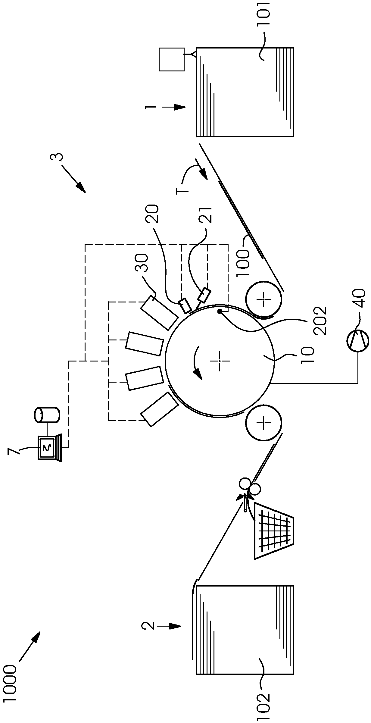
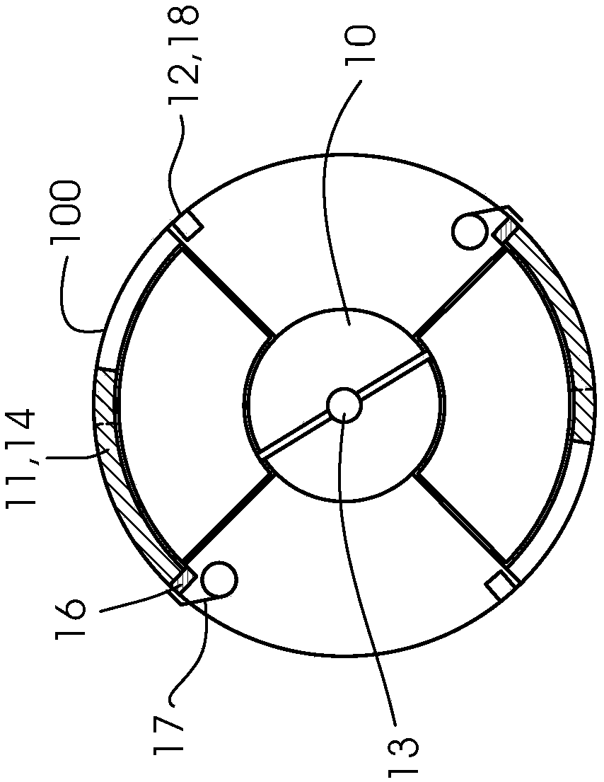
[0028] figure 1 A digital printing press 1000 for printing on sheets 100 is shown. The digital printing machine 1000 has a digital printing station 3 with a plurality of inkjet printing strips 30 arranged one behind the other in the conveying direction T, the inkjet printing strips 30 having inkjet printing strips 30 arranged parallel to one another. printing head. The sheets 100 from a feeder stack 101 in the sheet feeder 1 are transported in a transport direction T to the digital printing station 3 using transport means, not shown in detail, such as transport belts and transport rollers, for example. The transport of the sheet 100 through the digital printing station 3 is via jet cylinder 10 (see Figure 2a and 2b ), the sheet 100 is placed on the spray cylinder 10 . A thermal imaging camera 20 and a so-called bad page sensor 21 , which are connected to the machine control 7 , are arranged upstream of the digital printing station 3 . As a result of the rotation of the...


PUM


Abstract

The invention relates to a method to control the placement of a printing material base on the delivery element of a printing machine. The method comprises following steps: (a) detecting a printing material base (100) on a delivery element (10) by a thermal imaging camera (20); (b) analyzing a thermal image (200) of the thermal imaging camera (20); (c) correcting a printing material holding device(9,15,18) so that the printing material base (100) can be better placed on the delivery element (10). The method has the advantage that the whole printing material base is reliably placed. The invention also relates to a printing machine (1000) for exerting the method.

Description

technical field [0001] The invention relates to a method for controlling the placement of a printing material substrate on a transport element with the features of claim 1 and to a printing machine with the features of claim 7 . Background technique [0002] Digital printing presses are known for printing sheets made of paper, cardboard and cardboard in small format or with individual printing themes. As the sheets are printed with the inkjet heads, the transport system moves the individual sheets past under the inkjet heads with minimal intervals. Carousel belts (eg, designed as suction belts) and rotating drums (so-called spray drums) or rotary trays are known as conveyor systems. [0003] In a machine concept using a cylinder, as described in DE 10 2015 211 440 B3, a plurality of inkjet print heads are arranged in a radially spaced manner above the jet cylinder, which print with respect to the printhead Move the passing pages in small intervals. On the jet cylinder, se...

Claims


Application Information

Patent Timeline
Patent Type & Authority Applications(China)
IPC IPC(8): B41F21/00B41F33/14B65H7/14
CPCB41F21/00B41F33/14B65H7/14B41J11/007B41J11/0095B41J13/0054B41J13/223B41F21/102B65H5/12B65H5/224B65H7/06B65H2406/33B65H2406/3622B65H2515/40B65H2515/20B65H2511/24B65H2220/01B65H2220/02B65H2220/03
Inventor T·施密特H-J·埃格诺尔夫
Owner HEIDELBERGER DRUCKMASCHINEN AG
Why Eureka
Try Eureka