
Carbon sliding plate preparation method

A carbon skateboard and product technology, applied in the field of rail transit, can solve the problems of carbon skateboard loss, metal bracket separation, affecting train running, etc., and achieve the effects of improving bonding performance, reducing separation, and increasing area

Inactive Publication Date: 2018-11-23
成都易卡朋电碳有限公司
View PDF6 Cites 1 Cited by
  • Summary
  • Abstract
  • Description
  • Claims
  • Application Information

AI Technical Summary

Problems solved by technology

[0003] Due to the fact that the carbon skateboard needs to withstand high-speed sliding and high-voltage and high-current conditions under normal work, the carbon skateboard will cause a certain degree of loss
At the same time, carbon skateboards usually include a metal bracket and a carbon body, and the carbon body is fixed on the metal bracket in the form of conductive glue, and when exposed to the sun for a long time, washed by rain or high-speed sliding, the metal bracket is easy to contact with the carbon body. Separation occurred, causing the carbon skateboard to fail to take power, affecting normal train running

Method used


Image

  • Carbon sliding plate preparation method
  • Carbon sliding plate preparation method
  • Carbon sliding plate preparation method

Examples


Embodiment 1

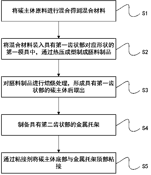
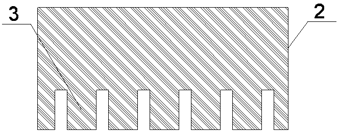
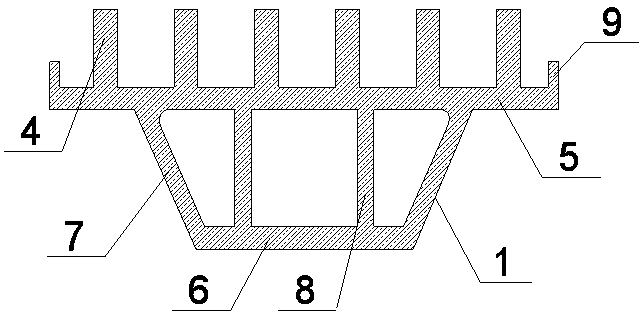
[0045] This embodiment provides a method for preparing a carbon sliding plate for a pantograph. Among them, the carbon skateboard completed with vegetation can be used on the electric traction locomotive, and used to obtain electric energy from the catenary to supply power to the electric traction locomotive, that is, to realize power extraction. The carbon slide plate is installed on the roof of the locomotive or motor vehicle. Such as Figure 4 As shown, the carbon skateboard includes: a metal bracket 1 and a carbon body 2 arranged on the metal bracket 1; wherein, the bottom of the carbon body 2 is provided with a plurality of first teeth 3, and the metal bracket The top of the frame 1 is provided with a second tooth-shaped portion 4 cooperating with the first tooth-shaped portion 3 , and the first tooth-shaped portion 3 and the second tooth-shaped portion 4 are bonded by an adhesive. Such as figure 1 As shown, the preparation method includes: S1: mixing the raw materials...

Embodiment 2

[0063] This embodiment provides a method for preparing a carbon sliding plate for a pantograph. Similar to Embodiment 1, the carbon skateboard can be used on an electric traction locomotive, and is used to obtain electric energy from the catenary to supply power to the electric traction locomotive, that is, to realize power extraction. The carbon slide plate is installed on the roof of the locomotive or motor vehicle. Such as Figure 4 As shown, the carbon skateboard includes: a metal bracket 1 and a carbon body 2 arranged on the metal bracket 1; wherein, the bottom of the carbon body 2 is provided with a plurality of first teeth 3, and the metal bracket The top of the frame 1 is provided with a second tooth-shaped portion 4 cooperating with the first tooth-shaped portion 3 , and the first tooth-shaped portion 3 and the second tooth-shaped portion 4 are bonded by an adhesive. Such as Figure 4 As shown, the preparation method includes: S1: mixing the raw materials of the ca...


PUM


Abstract

The invention discloses a carbon sliding plate preparation method which includes the steps: S1 mixing carbon body (2) raw materials to obtain a mixed material; S2 placing the mixed material into a first die with a shape corresponding to a first tooth portion (3), and performing hot-press forming on the mixed material to prepare a blank product; S3 roasting the blank product to form a carbon body (2) with the first tooth portion (3), and taking out the carbon body (2); S4 preparing a metal bracket (1) with a second tooth portion (4); S5 adhering the bottom of the carbon body (2) and the top ofthe metal bracket (1) by adhesives. The area of the adhesive surface of a prepared carbon sliding plate is increased, adhesive properties are further improved, and separation between the metal bracketand the carbon body is effectively reduced.

Description

technical field [0001] The invention relates to the field of rail transit, in particular to the field of electric carbon products for rail transit, and in particular to a method for preparing a carbon slide. Background technique [0002] Electric traction locomotives are installed on the roof of locomotives or motor cars, which obtain electrical energy from the catenary. Pantographs can be divided into single-arm bows and double-arm bows, both of which are composed of slide plates, upper frames, lower arm rods (lower frames for double-arm bows), underframes, bow springs, transmission cylinders, supporting insulators and other components. The load current passes through the contact surface of the contact wire and the pantograph sliding plate, which is related to the contact pressure, transition resistance, and contact area between the sliding plate and the contact wire, and depends on the interaction between the pantograph and the catenary. The prior art mostly adopts the fo...

Claims


Application Information

Patent Timeline
Patent Type & Authority Applications(China)
IPC IPC(8): B60L5/20C04B35/52C09J5/00
CPCB60L5/205C04B35/52C09J5/00
Inventor 母益强
Owner 成都易卡朋电碳有限公司
Learn More