
Hydraulic brake slide block system

A technology of hydraulic braking and sliding block, applied in the field of machinery, can solve the problem that the workpiece cannot be guaranteed to stop at a fixed station, etc., and achieve the effect of simple structure and easy operation.

Active Publication Date: 2018-11-23
WUHAN MARINE MACHINERY PLANT
View PDF3 Cites 0 Cited by
  • Summary
  • Abstract
  • Description
  • Claims
  • Application Information

AI Technical Summary

Problems solved by technology

[0005] In order to solve the problem in the prior art that the workpiece cannot be guaranteed to stop at the fixed station every time, the embodiment of the present invention provides a hydraulic brake slider system

Method used


Image

  • Hydraulic brake slide block system
  • Hydraulic brake slide block system
  • Hydraulic brake slide block system

Examples


Embodiment Construction

[0028] In order to make the object, technical solution and advantages of the present invention clearer, the implementation manner of the present invention will be further described in detail below in conjunction with the accompanying drawings.

[0029] In order to better understand the present invention, the following briefly describes the application scenarios of the hydraulic brake slider system:

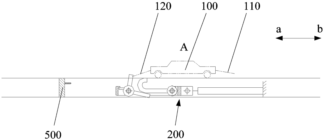
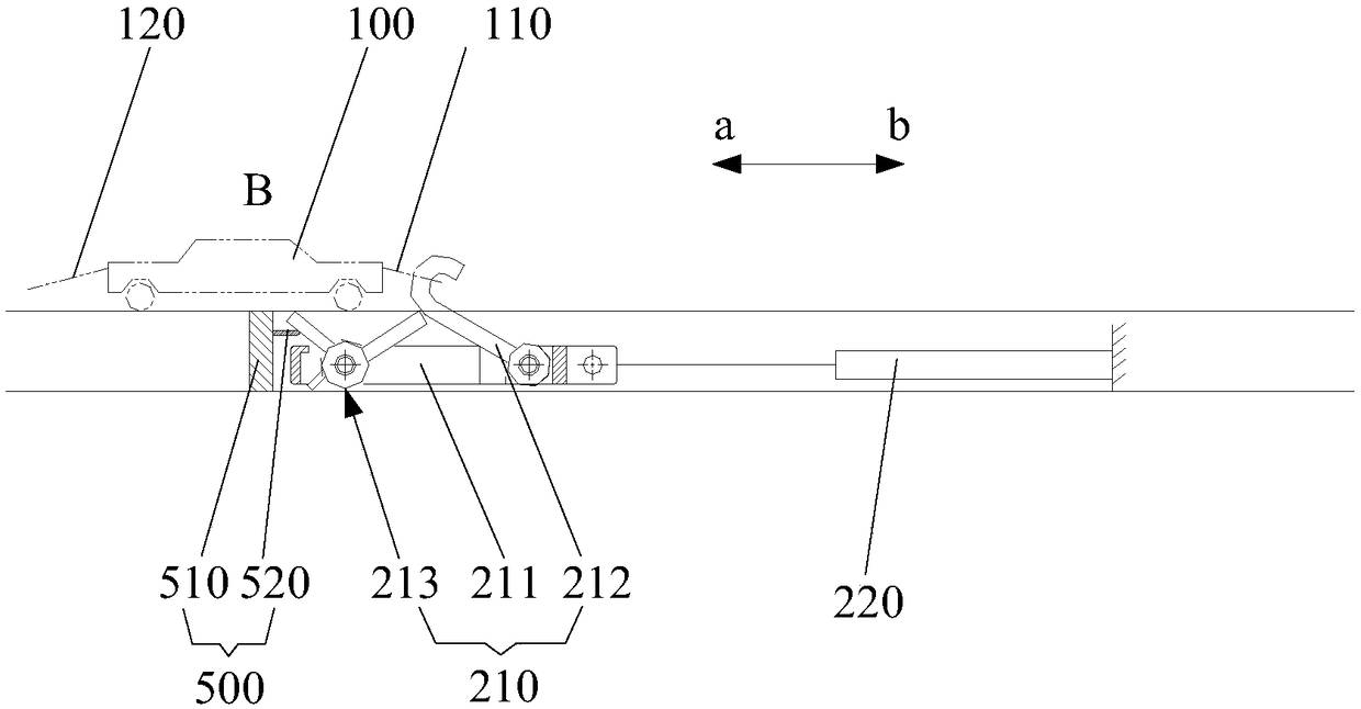
[0030] figure 1 It is a schematic diagram of the use of a hydraulic brake slider system provided by the embodiment of the present invention, such as figure 1 As shown, the workpiece 100 is set above a horizontal plane and is at the starting position A, one end of the workpiece 100 is provided with a brake lever 110, and the other end of the workpiece 100 is provided with a fork 120, and the workpiece 100 moves from the starting position at a certain initial speed. A moves in the direction a to the end position B, the hydraulic brake slider system 200 is arranged below the horizon...


PUM


Abstract

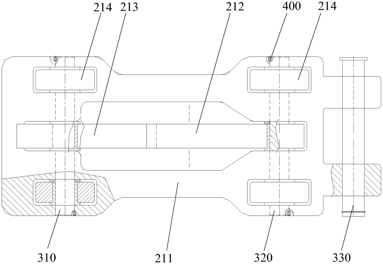
The invention discloses a hydraulic brake slide block system and belongs to the technical field of machinery. The hydraulic brake slide block system comprises a slide block mechanism and a hydraulic mechanism, wherein one end of the slide block mechanism is connected with the hydraulic mechanism, the slide block mechanism comprises a slide block support, a braking hook and a rotary assembly, the braking hook and the rotary assembly are hinged to the slide block support, and the braking hook is arranged on the rotary assembly. When a workpiece has certain initial speed and moves from an initialposition to a destination position in the first direction, a shifting fork of the workpiece pushes the rotary assembly to move in a vertical plane in the first direction, and the hydraulic mechanismprovides braking power for the slide block mechanism and makes the workpiece finally stop at the destination position. The rotary assembly drives the braking hook to rotate in the vertical plane in the vertical direction, so that the braking hook is locked with a braking rod together. If the final stop position of the workpiece exceeds the destination position, the hydraulic mechanism can drive the slide block mechanism to move toward the second direction, the slide block mechanism moves towards the second direction through the braking hook pulling the workpiece, so that the workpiece finallystops at the destination position.

Description

technical field [0001] The invention relates to the technical field of machinery, in particular to a hydraulic brake slider system. Background technique [0002] In an assembly line, a workpiece needs to move from the starting position to the end position within a fixed stroke, and the workpiece has a certain initial velocity. Therefore, in order to ensure that the workpiece can stop at the end position, it is necessary to It is buffered and braked until the workpiece stops at the fixed station. [0003] The method adopted at present is usually to set a brake mechanism on the workpiece, and when it reaches the end position soon, the brake mechanism is controlled to start, so that the workpiece is decelerated, and finally reaches the end position. [0004] However, due to the fact that the braking time and the braking force of the braking mechanism cannot be controlled to be consistent at each braking time, there will be deviations in the final position of the workpiece afte...

Claims


Application Information

Patent Timeline
IPC IPC(8): B60T1/14
CPCB60T1/14B60T2201/03
Inventor 程旎汪洋李克飞王正李海席志成高卓
Owner WUHAN MARINE MACHINERY PLANT
Learn More