
Electric vehicle hydraulic brake system

A technology for hydraulic braking and electric vehicles, applied in braking safety systems, brakes, brake transmissions, etc., can solve the problem of increasing the manufacturing and maintenance costs of electric buses, unable to maintain stable working performance, and low control accuracy and response speed. and other problems, to achieve the effect of stable and reliable working performance, solving insufficient braking force and difficult to control deviation

Pending Publication Date: 2018-11-23
云南兴长江实业有限公司
View PDF5 Cites 1 Cited by
  • Summary
  • Abstract
  • Description
  • Claims
  • Application Information

AI Technical Summary

Problems solved by technology

The steering, braking, and parking execution systems of automobiles in the prior art mostly use a combination of hydraulic power steering and pneumatic braking. Since the pneumatic braking needs to be filled with the air pump every time before it can be used, it takes a lot of time to start the car. It takes a long time to charge the air pump, which increases the start-up time of the vehicle, and the reliability of the pneumatic brake system is relatively poor compared with hydraulic brakes. It cannot maintain stable working performance under high-speed motion or bumpy conditions, thus affecting the safe driving of the car.
The existing hydraulic braking device has a large volume, complex structure, low control accuracy and low response speed. On the other hand, the installation space on the vehicle is limited, which increases the manufacturing and maintenance costs of electric buses. The hydraulic braking device is made of electric vehicles. The power provided by the dynamic control system is an important guarantee for the braking safety performance of new energy buses

Method used


Image

  • Electric vehicle hydraulic brake system
  • Electric vehicle hydraulic brake system
  • Electric vehicle hydraulic brake system

Examples


Embodiment Construction

[0017] The present invention will be further described below in conjunction with the accompanying drawings, but the present invention is not limited in any way. Any transformation or replacement based on the teaching of the present invention belongs to the protection scope of the present invention.

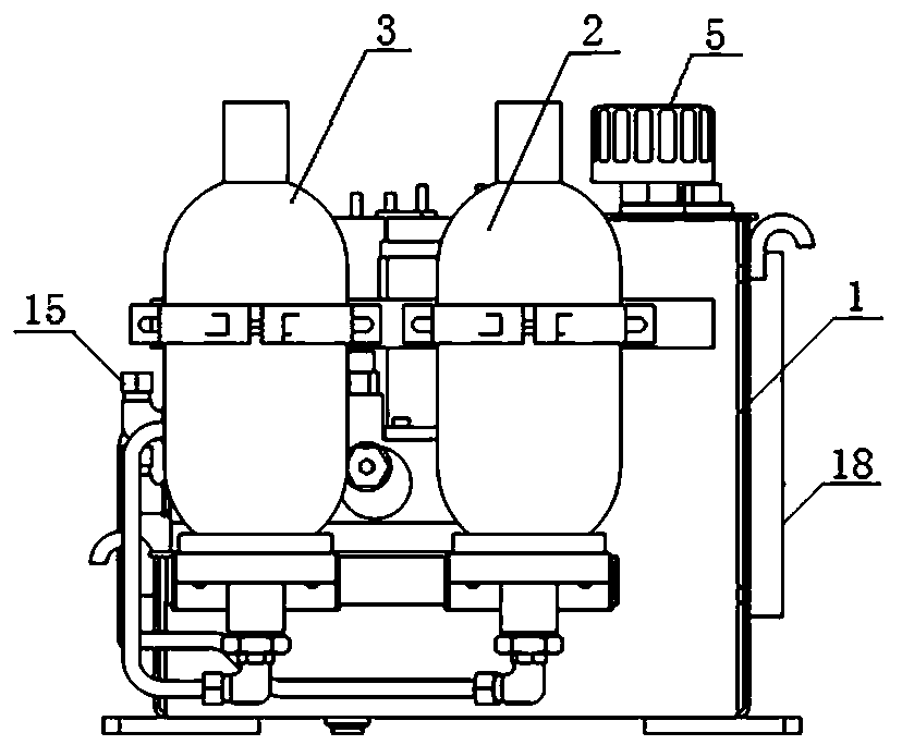
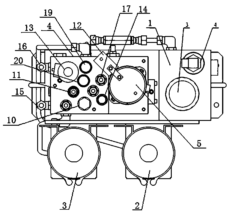
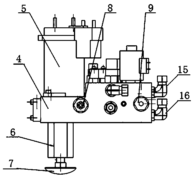
[0018] as attached Figure 1~5 The electric vehicle hydraulic braking system shown includes a fuel tank 1, a hydraulic brake valve and an energy storage mechanism arranged on the fuel tank 1, the hydraulic brake valve is connected to the energy storage mechanism through pipelines, and the energy storage mechanism is respectively connected through pipelines. Connect the front axle brake, rear axle brake, and parking brake commutator. The front axle brake, rear axle brake, and parking brake commutator are connected back to the hydraulic brake valve through the brake oil return pipe. The hydraulic brake valve It is arranged on the top of the fuel tank 1, and the hydraulic brake valve...


PUM


Abstract

The invention discloses an electric vehicle hydraulic brake system. The electric vehicle hydraulic brake system comprises an oil tank, a hydraulic brake valve and an energy storage mechanism, whereinthe hydraulic brake valve and the energy storage mechanism are arranged on the oil tank; the hydraulic brake valve is connected to the energy storage mechanism through a pipeline, the energy storage mechanism is separately connected to a front axle brake, a rear axle brake and a parking brake commutator through pipelines, the front axle brake, the rear axle brake and the parking brake commutator are separately connected to the hydraulic brake valve through a brake oil return pipe, the hydraulic brake valve is disposed on the top of the oil tank and extends downward into the oil tank, the energy storage mechanism is disposed on the front surface or back surface of the oil tank, the hydraulic brake valve is connected to the energy storage mechanism through a pipeline, one end of the brake oil return pipe is connected to the hydraulic brake valve, and the other end of the brake oil return pipe is connected to the front axle brake, the rear axle brake and the parking brake commutator through pipelines. The electric vehicle hydraulic brake system is high in brake control precision and response speed and excellent in anti-interference capability, the vehicle speed is reduced smoothly ina braking process, the braking direction is stable, and the operation is quiet.

Description

technical field [0001] The invention belongs to the technical field of automobile hydraulic braking, and in particular relates to an electric automobile hydraulic braking system with strong anti-interference ability, stable working performance and quiet operation. Background technique [0002] With the increasing scarcity of oil resources in the world, the increasingly intensified conflict with the dependence of traditional fuel vehicles on oil, and the increasingly serious large-scale smog, the automotive industry, which is a large energy-consuming and emission-intensive industry, plays an important role in the energy-saving and emission-reduction strategy. choose. Facing the ensuing energy and environmental problems, China has listed the energy-saving, environmentally friendly, intelligent, and safe electric vehicle industry as an emerging strategy for key development. [0003] The pump station in the electric vehicle hydraulic braking system is a kind of electric motor i...

Claims


Application Information

Patent Timeline
IPC IPC(8): B60T13/14B60T17/22
CPCB60T13/14B60T17/22
Inventor 叶艺明张剑张沧李维举鲍强
Owner 云南兴长江实业有限公司
Learn More