Grooving device for cement concrete road pavement for highway engineering
What is Al technical title?
Al technical title is built by PatSnap Al team. It summarizes the technical point description of the patent document.
A technology for cement concrete and engineering, applied in the field of cement concrete pavement carving devices for highway engineering, can solve problems such as difficulty in mastering, easily affected spacing between adjacent grooves, manual push, etc., to ensure quality and aesthetics, novel structural design, Apply convenient effects
Inactive Publication Date: 2018-11-23
HEFEI JINGMEI GRAPHIC TECH CO LTD
View PDF0 Cites 3 Cited by
Summary
Abstract
Description
Claims
Application Information
AI Technical Summary
This helps you quickly interpret patents by identifying the three key elements:
Problems solved by technology
Method used
Benefits of technology
Problems solved by technology
[0004] The purpose of the present invention is to provide a cement concrete pavement groove device for highway engineering, to solve the problem that the forward direction of the groove machine is affected by manual control and difficult to grasp, the distance between adjacent grooves is easily affected, and even The engraving is biased and heavy, and the control of the groove depth is also difficult, which is not conducive to the beauty and order of the road surface texture, and most of them use manual push, which is time-consuming and laborious; secondly, in the cutting process, for The depth of the grooving cannot be adjusted according to the requirements; the problem that a good grooving trajectory cannot be determined according to the calibration during the grooving process
Method used
Image
Click on the blue label to locate the original text in one second.
Reading with bidirectional positioning of images and text.
Examples
Embodiment Construction
[0022] The technical solutions of the present invention will be clearly and completely described below in conjunction with the embodiments. Apparently, the described embodiments are only some of the embodiments of the present invention, not all of them. Based on the embodiments of the present invention, all other embodiments obtained by persons of ordinary skill in the art without creative efforts fall within the protection scope of the present invention.
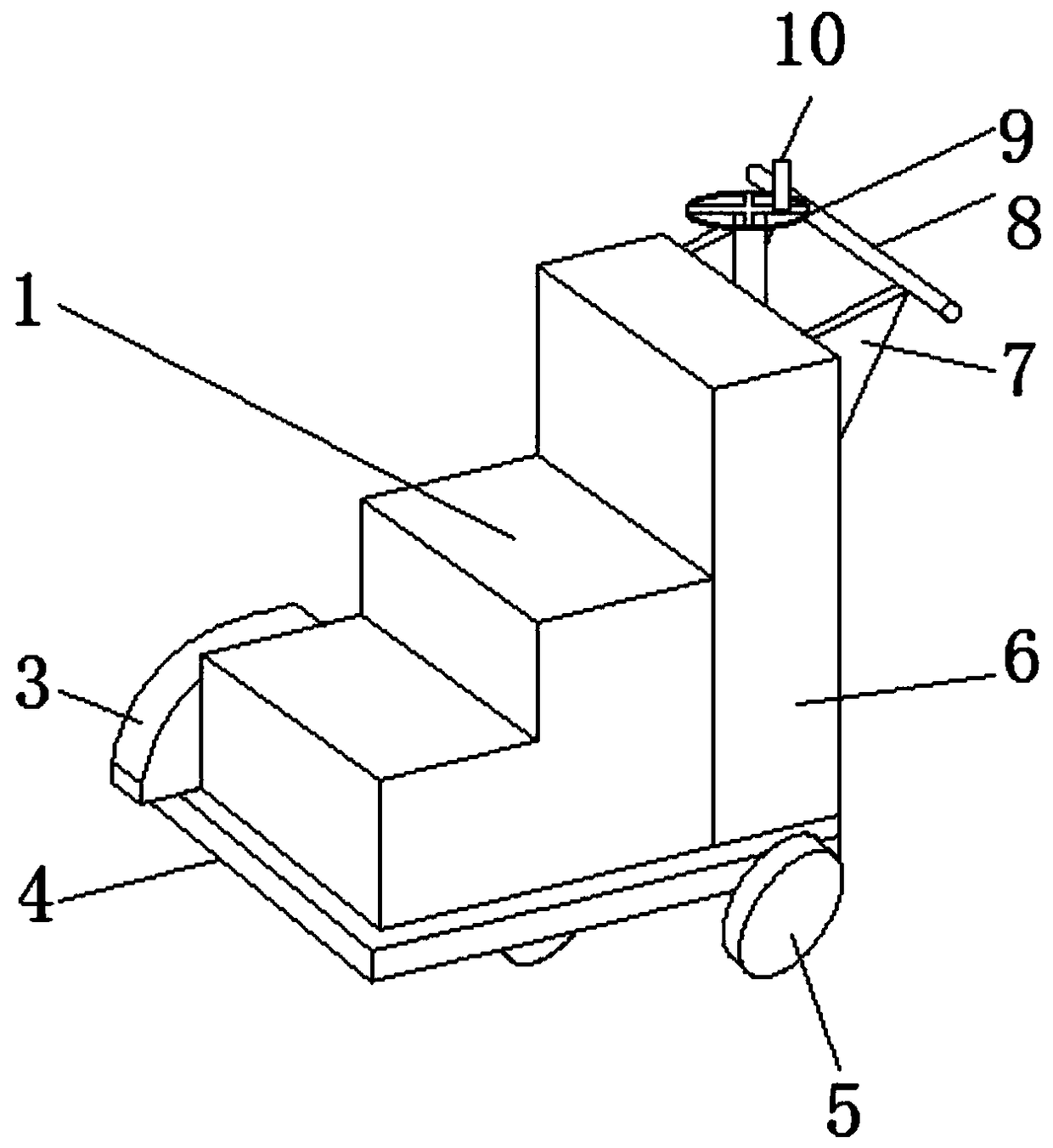
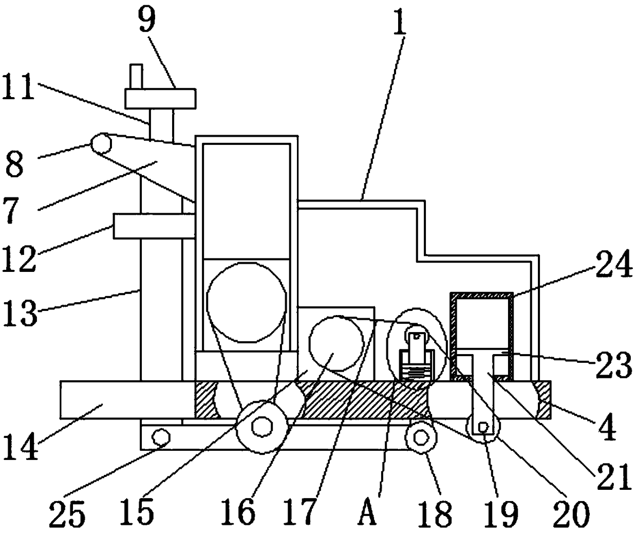
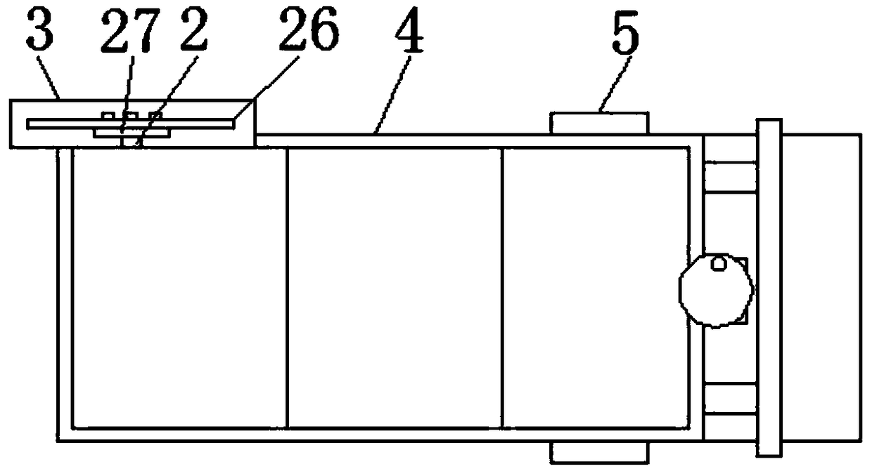
[0023] Such as Figure 1-5 Shown, a kind of cement concrete pavement engraving device for highway engineering, comprises shell 1, driving shaft 2, dustproof cover 3, base plate 4, rear wheel 5, driving box 6, connecting plate 7, push rod 8, turntable 9, crank 10, steering shaft 11, fixed plate 12, fixed rod 13, pedal 14, first motor 15, driving gear 16, chain 17, steering wheel 18, first rotating shaft 19, transmission gear 20, lifting plate 21, Drive pulley 22, piston 23, hydraulic cylinder 24, steering knuckle 25, saw di...
PUM
Abstract
The invention discloses a grooving device for a cement concrete road pavement for highway engineering. The grooving device comprises an outer casing, a drive shaft, a dustproof cover, a bottom plate,a back wheel, a drive box, a connecting plate, a push rod, a rotary disc, a rocking handle, a steering shaft, a fixed plate, a fixed rod, a pedal plate, a first motor, a drive gear, a chain, a steering wheel, a first rotary shaft, a drive gear, a lifting plate, a drive belt wheel, a piston, a hydraulic cylinder, a steering joint, a saw disc, a fixed disc, a transition gear, a support rod, a rectangular box, a blocking plate, a compression spring, a second motor and a drive belt wheel, wherein the outer casing is arranged at the left side of the top part of the bottom plate; the drive box is arranged at the right side of the outer casing; a hydraulic cylinder is fixedly arranged at the left side of the bottom surface of the interior of the outer casing; the piston is arranged in the hydraulic cylinder; the lifting plate is fixedly welded under the piston; the first rotary shaft is arranged at the bottom part of the lifting plate. The grooving device has the advantages that the groovingdepth can be adjusted, and the straightness of the grooving line is guaranteed.
Description
technical field [0001] The invention relates to the field of road engineering equipment, in particular to a cement concrete pavement carving device for road engineering. Background technique [0002] Highway engineering refers to the investigation, measurement, design, construction, maintenance and management of highway structures. Highway engineering structures include: roadbeds, road surfaces, bridges, culverts, tunnels, drainage systems, safety protection facilities, greening and traffic monitoring facilities, as well as houses, workshops and other service facilities used for construction, maintenance and monitoring. , the grooves on the surface of cement concrete pavement are more and more widely used. The longitudinal grooves can not only effectively reduce tire road noise, but also effectively reduce the probability of vehicle sideslip; the transverse grooves speed up the drainage speed of the road surface and increase the Therefore, with the development of cement con...
Claims
Application Information
Patent Timeline
Application Date:The date an application was filed.
Publication Date:The date a patent or application was officially published.
First Publication Date:The earliest publication date of a patent with the same application number.
Issue Date:Publication date of the patent grant document.
PCT Entry Date:The Entry date of PCT National Phase.
Estimated Expiry Date:The statutory expiry date of a patent right according to the Patent Law, and it is the longest term of protection that the patent right can achieve without the termination of the patent right due to other reasons(Term extension factor has been taken into account ).
Invalid Date:Actual expiry date is based on effective date or publication date of legal transaction data of invalid patent.