Water discharge pipeline cleaning device

A technology for drainage pipes and cleaning devices, which is applied to water supply devices, waterway systems, buildings, etc., can solve problems such as inconvenient operation, small pipeline flow, and limited drainage of drainage pipes, and achieve the effect of improving cleaning efficiency.

Active Publication Date: 2018-11-23
海腾创建(深圳)集团有限公司
View PDF9 Cites 11 Cited by
  • Summary
  • Abstract
  • Description
  • Claims
  • Application Information

AI Technical Summary

Problems solved by technology

[0002] With the continuous development of urban construction, the drainage pipes under the urban roads have been silted for a long time, and there is a large amount of silt. If it is too large, unknown objects will be flushed into the drainage pipe and cause the blockage of the pipe
For a long time, in severe weather such as heavy rains, the amount of precipitation is large, and the drainage of drainage pipes is limited. On the one hand, the sewage containing a large number of bacteria in the sewer will be poured back to the road surface, bringing a large number of pathogenic bacteria, and damaging people's health. On the other hand, the sewage cannot be discharged in time, which seriously affects people's normal travel.
[0003] The dredging and sundries of urban underground drainage pipes in the prior art are mainly divided into two forms, one is machine dredging, and the other is manual excavation. For drainage pipes with larger diameters, whether mechanical equipment or manual dredging, It is relatively convenient, but for general urban sewage drainage pipes, the diameter of the drainage pipe is about 1.5m, and large-scale dredging equipment cannot enter, and manual dredging is not convenient for operation due to the narrow space in the drainage pipe

Method used


Image

  • Water discharge pipeline cleaning device
  • Water discharge pipeline cleaning device
  • Water discharge pipeline cleaning device

Examples


Embodiment Construction

[0040] The present invention will be described in further detail below in conjunction with the accompanying drawings.

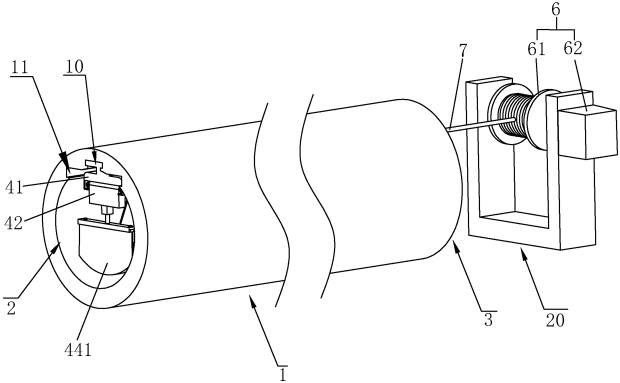
[0041] A kind of drain pipe cleaning device, with reference to figure 1 and figure 2 , including a cylindrical drainage pipe 1, the drainage pipe 1 is respectively provided with a water inlet 2 and a water outlet 3; at the same time, the top of the inner wall of the drainage pipe 1 is sequentially slid from the water inlet 2 to the water outlet 3 and connected with scraping and drainage The mud scraping assembly and the driving trolley 5 of the silt on the inner wall of the pipeline 1 are arranged along the length direction of the drainage pipeline 1, and the mud scraping assembly and the driving trolley 5 are fixedly connected.

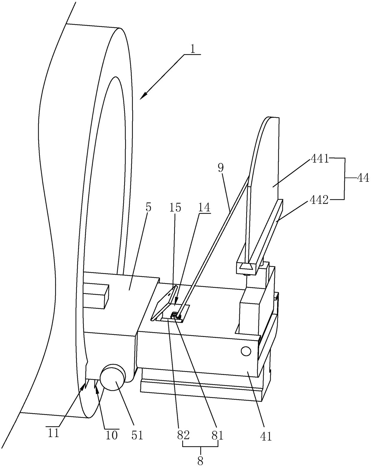
[0042] refer to figure 2 and image 3 ,, the surface of the driving trolley 5 facing away from the drainage pipe 1 is equipped with a driving member 52 for driving the movement of the driving trolley 5 (refer to Figure 4 ), i...


PUM


Abstract

The invention relates to the technical field of silt cleaning equipment, in particular to a water discharge pipeline cleaning device. The water discharge pipeline cleaning device is mainly characterized by comprising a water discharge pipeline, wherein the water discharging pipeline is respectively provided with a water inlet and a water outlet; the water discharge pipeline is glidingly and movably connected with a mud scraping assembly and a driving trolley; the mud scraping assembly is connected with the driving trolley; a driving element is arranged on the driving trolley; the mud scrapingassembly comprises a fixing block, a scraper base, a telescopic mechanism and a scraping tool; the fixing block is rotationally provided with a rotating shaft; the scraper base is arranged on the rotating shaft; a torsional spring is sleeved and connected onto the rotating shaft; the scraping tool is connected with the scraper base through the telescopic mechanism; a first winding assembly and a pull rope are arranged in the water outlet position; the fixing block is provided with a second winding assembly and a steel wire rope; when the scraping tool rotates to a first angle, the scraping tool can rotate to clean silt; when the scraping tool rotates to the second angle, the scraping tool can rotate to extend out of the water inlet. The device has the advantages that the automatic cleaningdegree of the water discharge pipeline is improved; the silt cleaning efficiency is further improved.

Description

technical field [0001] The invention relates to the technical field of sludge cleaning equipment, more specifically, it relates to a drainage pipe cleaning device. Background technique [0002] With the continuous development of urban construction, the drainage pipes under the urban roads have been silted for a long time, and there is a large amount of silt. If it is too large, unknown objects will be flushed into the drainage pipe and cause the blockage of the pipe. For a long time, in severe weather such as heavy rains, the amount of precipitation is large, and the drainage of drainage pipes is limited. On the one hand, the sewage containing a large number of bacteria in the sewer will be poured back to the road surface, bringing a large number of pathogenic bacteria, and damaging people's health. On the other hand, the sewage cannot be discharged in time, which seriously affects people's normal travel. [0003] The dredging and sundries of urban underground drainage pip...

Claims


Application Information

Patent Timeline
IPC IPC(8): E03F7/10
CPCE03F7/10
Inventor 吴兴华张佳佳付帅林成杰
Owner 海腾创建(深圳)集团有限公司
Why Eureka
Try Eureka