Boundary pumping control method for supersonic velocity knocking stabilizing and self-maintaining

A control method and supersonic technology, applied in the direction of combustion method, lighting and heating equipment, jet propulsion device, etc., can solve the problems of not considering the implementation of engine application, weakening detonation intensity, reducing engine thrust performance, etc., so as to avoid multiple detonations and Knocking and knocking out to achieve dynamic and stable effects

Pending Publication Date: 2018-11-23
NAT UNIV OF DEFENSE TECH
View PDF0 Cites 6 Cited by
  • Summary
  • Abstract
  • Description
  • Claims
  • Application Information

AI Technical Summary

Problems solved by technology

In these basic studies, a hot jet tube that independently supplies fuel and oxidant is used for hot jet injection and ignition and detonation, without considering the specific engine application.
In addition, for the dynamic stability control of detonation in supersonic airflow, Cai Xiaodong et al. carried out numerical simulation research, which proved that thermal jet injection can realize the dynamic stability control function of detonation in supersonic airflow to a certain extent, but it does not involve specific Thermal Jet Control Method Impl

Method used


Image

  • Boundary pumping control method for supersonic velocity knocking stabilizing and self-maintaining
  • Boundary pumping control method for supersonic velocity knocking stabilizing and self-maintaining

Examples


Embodiment Construction

[0022] In order to make the technical solutions and advantages of the present invention clearer, the present invention will be further described in detail below in conjunction with the accompanying drawings and embodiments. It should be understood that the specific embodiments described here are only used to explain the present invention, not to limit the present invention.

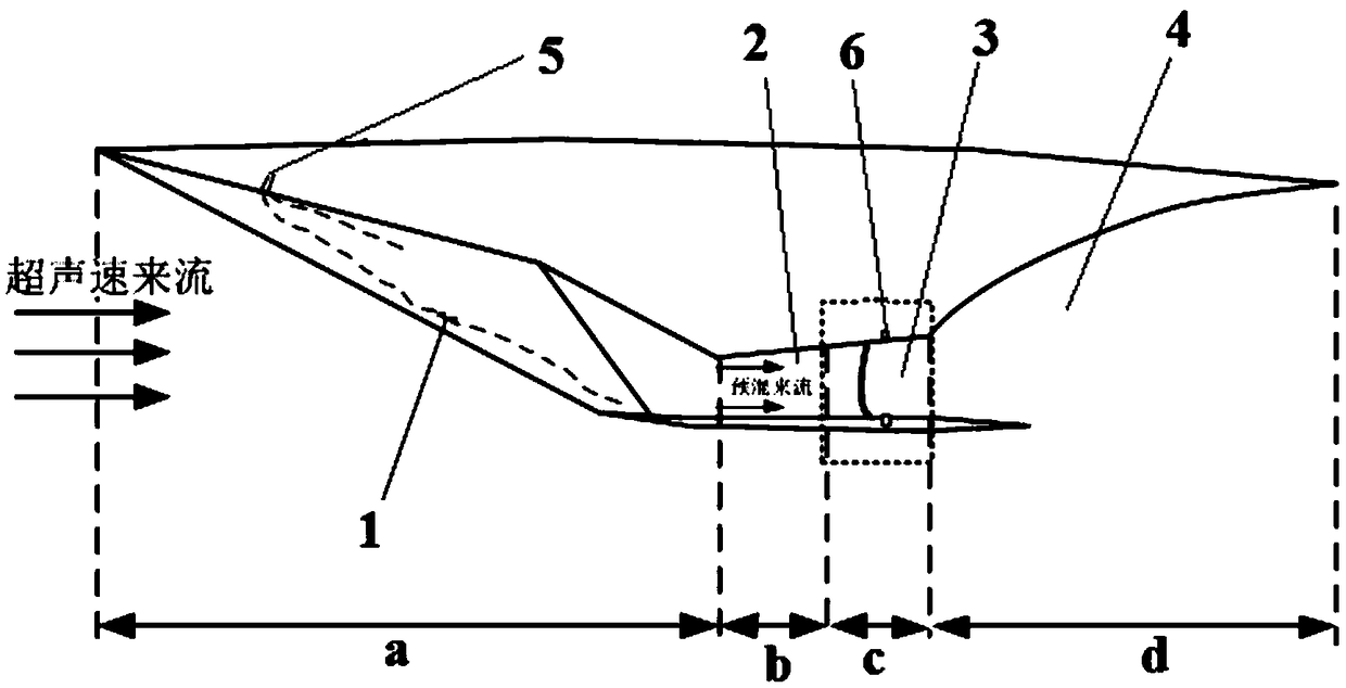
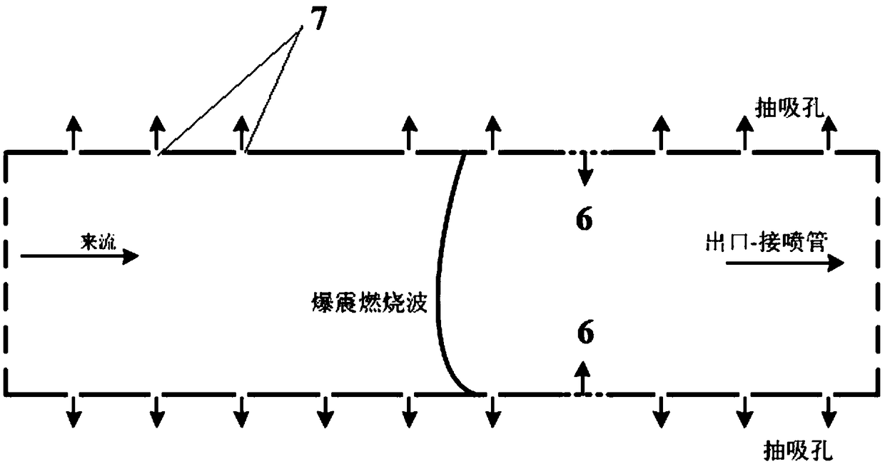
[0023] The invention provides a stable and self-sustaining boundary suction control method for supersonic detonation. In a novel scramjet engine based on detonation combustion, the effective detonation of supersonic combustible gas in the combustion chamber can be achieved through suction and thermal jet detonation, ensuring detonation Stabilization of the shock wave, thus ultimately achieving stable thrust performance.

[0024] refer to figure 1 and figure 2 , figure 1 Schematic diagram of the structure of a new type of scramjet engine based on detonation combustion, figure 2 It is a schematic diag...


PUM


Abstract

The invention provides a boundary pumping control method for supersonic velocity knocking stabilizing and self-maintaining. A supersonic combustion ramjet engine in the method comprises a gas input channel, an isolating section, a combustion chamber and a supersonic velocity spraying pipe. A heat jet flow hole for heat jet flow in a heat jet flow pipe to be sprayed out is arranged in the combustion chamber of the engine. A plurality of pumping holes are formed in the inner walls, before and behind the heat jet flow hole, of the combustion chamber. The pumping holes communicate with a pumping pump through pipelines. When the heat jet flow is adopted for carrying out knocking detonating in supersonic velocity airflow, the pumping pump and the pumping holes pump the airflow of an inner boundary layer of the combustion chamber in a pumping manner, and meanwhile, the heat jet flow is sprayed in to achieve knocking detonating. According to the method, in the knocking detonating process, thepumping pump is started, the pumping holes pump the airflow of the low-speed area of the inner boundary layer of the combustion chamber, the mutual effect between detonating knocking waves and the boundary layer is restrained to prevent forward passing of combustion waves, the influence of the boundary layer to detonating of the knocking waves is eliminated, and therefore the knocking waves can betransferred in the combustion chamber dynamically and stably.

Description

technical field [0001] The invention relates to the technical field of self-sustained propagation control of detonation waves in supersonic airflows, in particular to a method for realizing dynamic and stable self-sustained propagation of detonation waves in supersonic airflows, and provides a feasible design scheme for realizing complete detonation combustion in detonation engines. Background technique [0002] The scramjet engine (Scramjet) has excellent performance under high Mach (Ma>5) flight conditions, and has become the preferred solution for the propulsion system of hypersonic aircraft. However, combined with the current research and the US X-51A flight test, it can be known that the acceleration performance of the scramjet demonstrator is not obvious, and the net thrust is relatively small. Therefore, based on current research, there is an urgent need to improve engine thrust performance. The scramjet engine is designed according to the Brayton isobaric combust...

Claims


Application Information

Patent Timeline
IPC IPC(8): F02K7/14F02C3/14F02C9/00F23R3/02
CPCF02C3/14F02C9/00F02K7/14F23R3/02F05D2240/35
Inventor 蔡晓东梁剑寒林志勇刘世杰陈伟强
Owner NAT UNIV OF DEFENSE TECH
Why Eureka
Try Eureka