A three-phase separation treatment system for oil sludge and sand and its application

A three-phase separation and treatment system technology, applied in the field of three-phase separation treatment system for oily sludge and sand, can solve the problems of difficult treatment of oily sludge, lack of a large amount of effective treatment, late start, etc., and achieve low assembly and maintenance costs, compact structure, Ease of maintenance

Active Publication Date: 2017-01-11
威海恒荣环保科技有限公司
View PDF3 Cites 0 Cited by
  • Summary
  • Abstract
  • Description
  • Claims
  • Application Information

AI Technical Summary

Problems solved by technology

However, other major oil fields in China have various problems such as late start, lack of a large number of effective methods for treating oily sludge, etc.
Although oily sludge treatment technology has developed rapidly in domestic oilfields in recent years, due to the immaturity and limitations of various new technologies, the treatment of oily sludge is still a difficult problem for domestic oilfields

Method used


Image

  • A three-phase separation treatment system for oil sludge and sand and its application
  • A three-phase separation treatment system for oil sludge and sand and its application
  • A three-phase separation treatment system for oil sludge and sand and its application

Examples


Embodiment 1

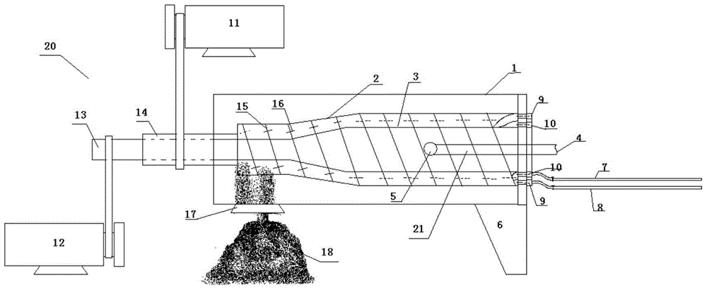
[0052] A three-phase separation treatment system for oil sludge and sand, comprising a heating and stirring tank for heating and stirring materials, and a three-phase separator 20 connected to the heating and stirring tank;

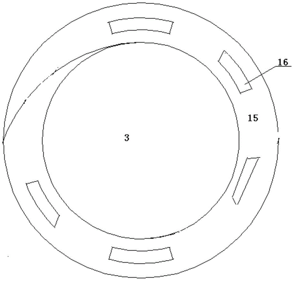
[0053] The three-phase separator 20 includes a stirring shaft drum 3, a centrifuge drum 2 is sheathed outside the stirring shaft drum 3, a propeller sheet 15 arranged on the outer wall of the stirring shaft drum 3, and a second motor for driving the stirring shaft drum 3 to rotate. Motor 12, the first motor 11 that drives the centrifugal cylinder 2 to rotate, and the axial rotation directions of the stirring shaft cylinder 3 and the centrifugal cylinder 2 are opposite;

[0054] The diameter of the stirring shaft cylinder 3 decreases successively along the axial direction of the feed; the diameter of the centrifuge 2 decreases sequentially along the axial direction of the feed; Compatible with the inner diameter;

[0055] A material channel 21 is axially ...

Embodiment 2

[0061] A treatment system for realizing the three-phase separation of oil, mud and sand as described in Embodiment 1, the difference is that the liquid phase return hole 16 is fan-shaped with the axis of the rotating shaft as the center.

Embodiment 3

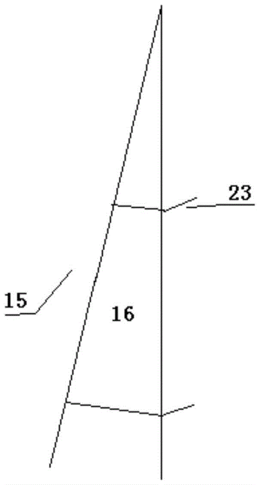
[0063] A treatment system for realizing the three-phase separation of oil, mud and sand as described in Example 2, the difference is that a flange 23 is provided around the liquid phase return hole 16 .


PUM

PropertyMeasurementUnit
lengthaaaaaaaaaa
diameteraaaaaaaaaa
sand contentaaaaaaaaaa

Abstract

The invention relates to an oil-sludge-sand three-phase separation treatment system which comprises a heating and stirring kettle for heating and stirring materials and a three-phase separation machine communicated with the heating and stirring kettle. According to the system, the rotary stirring of the materials is enhanced by a centrifugal barrel and a stirring rotating shaft barrel, which rotate in opposite directions, and meanwhile, the materials are subjected to three-phase separation under a centrifugal force generated by high-speed rotation of the centrifugal barrel; since a screw blade is mutually attached to the inner wall of the centrifugal barrel, a sand phase is conveyed to a sand phase discharge opening as the screw blade rotates, and an oil phase and a water phase are closely attached to the screw blade under the action of the centrifugal force and finally flow back to the large-diameter end of the centrifugal barrel along liquid-phase reflux holes in the screw blade; and according to the stratification condition of the water phase and the oil phase on the wall of the centrifugal barrel, namely that the water phase is closely attached to the inner wall of the centrifugal barrel under the action of the centrifugal force, followed by the oil phase, a water phase outlet and an oil phase outlet are concentrically formed in the large-diameter end of the centrifugal barrel respectively so as to lead the water phase and the oil phase out respectively.

Description

technical field [0001] The invention relates to a three-phase separation treatment system for oily sludge and sand and its application, and belongs to the technical field of oily sludge treatment. Background technique [0002] The treatment of oily sludge in oil fields is still an unsolved environmental problem at home and abroad. Especially in our country, the production of oily sludge is far greater than that of foreign oil fields, and the major oil fields and scientific workers in our country have not yet come up with effective solutions, which undoubtedly places a heavy burden on my country's oil extraction industry. burden. At present and for a period of time in the future, the treatment of oily sludge will be a hot spot in solid waste treatment. At present, there is still a big gap between the treatment and comprehensive utilization of oily sludge in my country and the advanced level in foreign countries. The treatment technology is backward, and the equipment Without ...

Claims


Application Information

Patent Timeline
Patent Type & Authority Patents(China)
IPC IPC(8): C02F11/00
Inventor 宋繁永
Owner 威海恒荣环保科技有限公司
Why Eureka
Try Eureka