Tunnel type drying oven

A drying oven and tunnel-type technology, which is applied in the field of tunnel-type drying ovens, can solve the problems of dust generation in the transmission system, increase production costs, and dust generation, and achieve the effects of stable structure, energy saving, and improved production efficiency

Active Publication Date: 2018-11-23
SHENZHEN TIME HIGH TECH EQUIP
View PDF4 Cites 0 Cited by
  • Summary
  • Abstract
  • Description
  • Claims
  • Application Information

AI Technical Summary

Problems solved by technology

But this drying method has at least the following defects: first, the transmission system of the transfer is prone to dust, oil and other pollution, so that the drying device can only be used in occasions where pollution control is not strict, and some materials, such as lithium batteries, are not The drying process in the production process requires no foreign dust, especially metal dust. The friction between gears and gears, gears and racks of the drying device with power source is easy to generate dust, which cannot meet the requirements; second, the drying device with power source The transfer device requires more power to maintain, consumes more energy, and increases production costs

Method used


Image

  • Tunnel type drying oven
  • Tunnel type drying oven
  • Tunnel type drying oven

Examples


Embodiment Construction

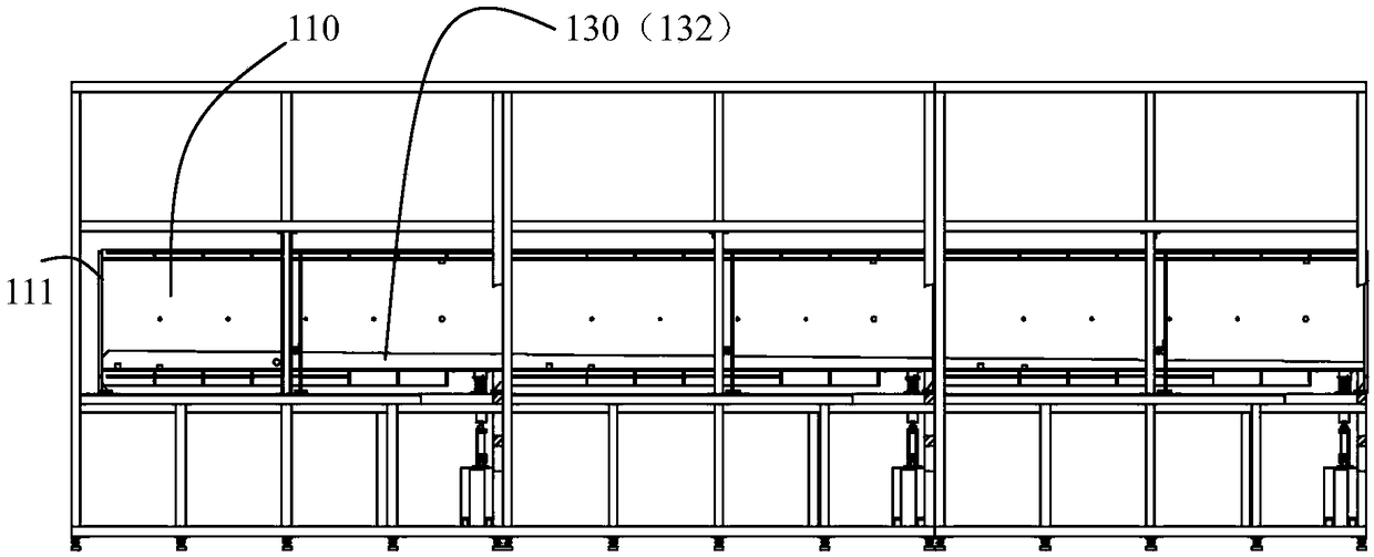
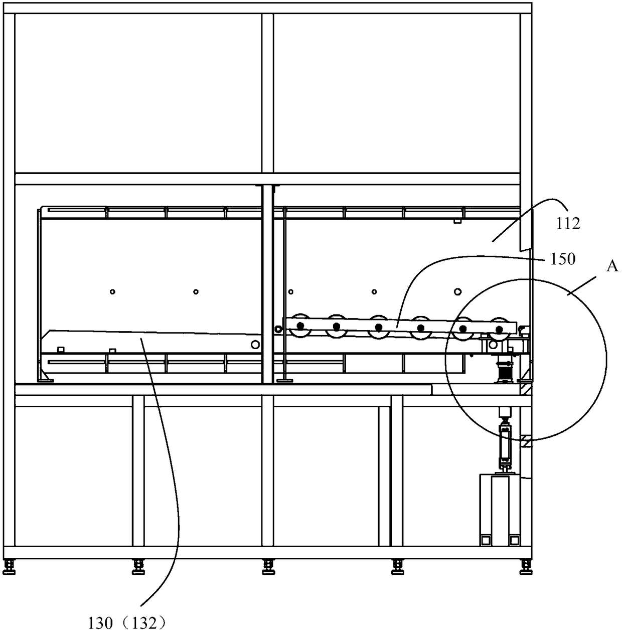
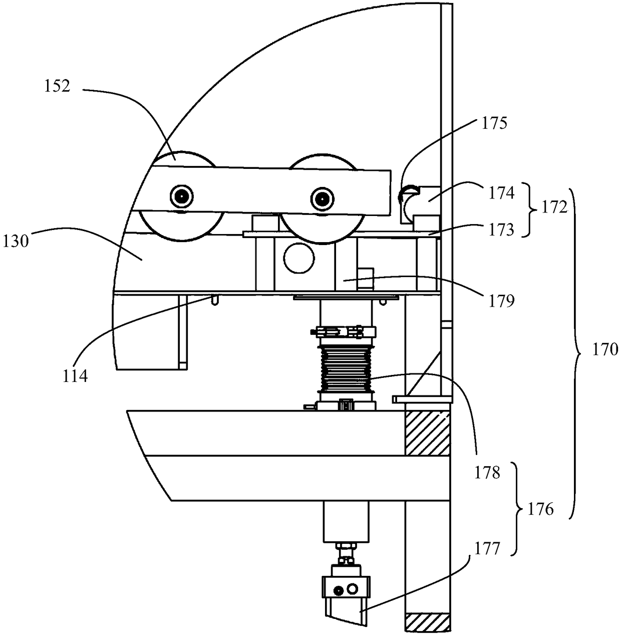
[0028] refer to Figure 1-Figure 3 , The first embodiment of the present invention provides a tunnel-type drying furnace, which mainly includes: a furnace body 110 , a guide rail 130 , and a transfer vehicle 150 . Body of furnace 110 comprises 3 furnace chambers 112 connected in sequence, all furnace chambers 112 are connected, and the inside of whole body of furnace 110 is an airtight cavity, promptly is provided with movable airtight door 111 at the head end and tail end of body of furnace, for Drying requires that the cavity be a vacuum or a near-vacuum cavity. In this embodiment, a movable airtight door (not shown in the figure) is also provided between adjacent furnace chambers 112 to ensure sufficient vacuum in each furnace chamber 112 . The furnace body 110 includes a bottom plate 114 , and the guide rail 130 is installed on the bottom plate 114 in this embodiment.

[0029] The guide rail 130 is laid inside the furnace body 110, and the guide rail 130 is inclined at a...


PUM


Abstract

The invention relates to a tunnel type drying oven. The tunnel type drying oven comprises an oven body, a guide rail, a transfer trolley, and a buffer positioning mechanism, wherein the guide rail spreads inside the oven body, and the guide rail tilts in the horizontal direction; the transfer trolley is matched with the guide rail for loading materials; the buffer positioning mechanism is mountedbelow the guide rail, and the buffer positioning mechanism comprises a buffer positioning part and a first drive part for providing power to the buffer positioning part; the buffer positioning part can move up and down relative to the guide rail; the oven body comprises a bottom plate; the first drive part comprises an air cylinder and a corrugated tube assembly; the air cylinder is used for driving the buffer positioning part; and the corrugated tube assembly is connected between the bottom plate and the air cylinder for sealing the oven body. The tunnel type drying oven is implemented, so that pollution can be reduced, energy can be saved, and cost can be reduced.

Description

[0001] This application is a divisional application of the application dated July 22, 2016, the national application number is 201610586916.9, and the title of the invention is "a tunnel-type drying furnace". 【Technical field】 [0002] The invention relates to the field of drying, in particular to a tunnel-type drying oven. 【Background technique】 [0003] Material drying devices are involved in many fields. Traditional material drying devices usually place the materials to be dried in a vacuum or near-vacuum chamber and dry them in a static state. The more mature drying devices on the market use a flowing production line, and the materials are driven on the production line through a power source to complete the drying process. But this drying method has at least the following defects: first, the transmission system of the transfer is prone to dust, oil and other pollution, so that the drying device can only be used in occasions where pollution control is not strict, and some...

Claims


Application Information

Patent Timeline
Patent Type & Authority Applications(China)
IPC IPC(8): F27B9/04F27B9/30F27B9/26
CPCF27B9/042F27B9/262F27B9/30
Inventor 田汉溶苏立宪
Owner SHENZHEN TIME HIGH TECH EQUIP
Why Eureka
Try Eureka