
Cover plate wear resistance test device

A test device and wear resistance technology, which is applied in the field of cover plate wear resistance test device, can solve the problems affecting the authenticity of test results and the reduction of positive pressure, etc., and achieve the effect of simple and practical device, stable pressure balance and easy replacement

Pending Publication Date: 2018-11-23
LENS TECH CHANGSHA
View PDF1 Cites 3 Cited by
  • Summary
  • Abstract
  • Description
  • Claims
  • Application Information

AI Technical Summary

Problems solved by technology

[0004] The existing wear resistance test device is as described in Chinese patent 201520862334.X, the grinding head assembly is located at one end of the guide link, the other end of the guide link is equipped with a runner and connected to the linkage mechanism, and the runner is located on the main body of the equipment In the set limit groove, because the thickness of the glass to be tested is different, when changing the glass of different thickness, the geometric axis line of the grinding head is not strictly perpendicular to the surface of the glass to be tested, and the guide rod is applied to the glass. The force in the horizontal direction will also generate a component force in the horizontal direction, so that the positive pressure actually received by the glass to generate friction force will be reduced, which will affect the authenticity of the test results. Therefore, this scheme is only suitable for the detection of glass with a fixed thickness.

Method used


Image

  • Cover plate wear resistance test device

Examples


Embodiment Construction

[0025] The embodiments of the present invention will be described in detail below with reference to the accompanying drawings, but the present invention can be implemented in various ways defined and covered by the claims.

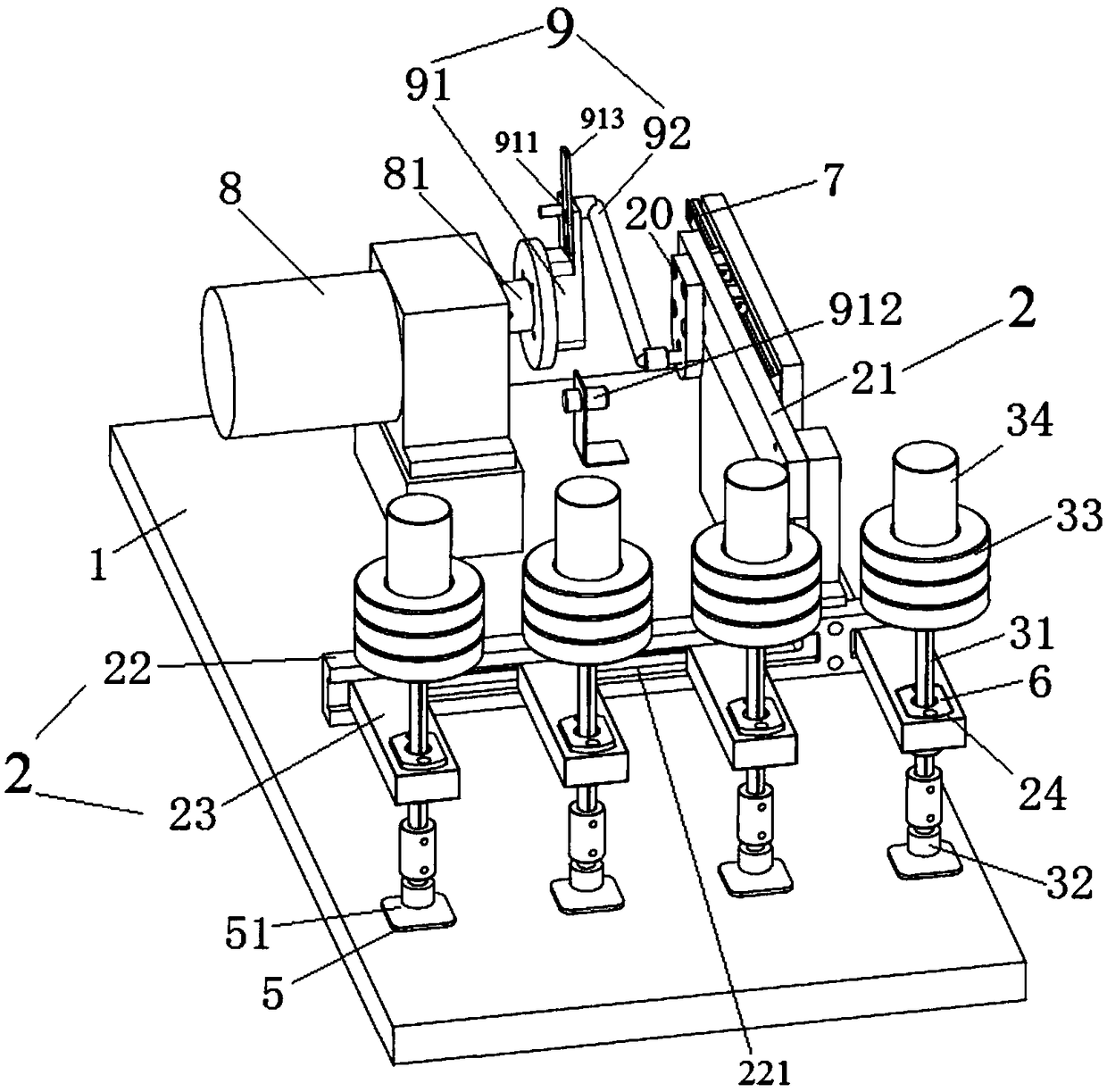
[0026] see figure 1 The test device for the wear resistance of the cover plate includes a bottom plate 1, a horizontal moving member 2 and a friction assembly 3 arranged on the bottom plate. The horizontal moving member can move back and forth along a straight track in the horizontal direction above the bottom plate, and the friction assembly is arranged on the horizontal moving member. Above, the friction assembly includes a vertical slide bar 31, a grinding head 32 and a counterweight 33, the length direction of the vertical slide bar is set along the vertical direction, the counterweight is pressed on the top of the vertical slide bar, and the grinding head is detachable Fixed at the bottom of the vertical slide bar, the end surface of the bottom of the...


PUM


Abstract

The invention provides a cover plate wear resistance test device, which comprises a bottom plate (1), a horizonal moving component (2) and a friction assembly (3), wherein the friction assembly comprises vertical slide rods (31), grinding heads (32) and balancing weights (33); the length direction of each vertical slide rod is arranged along the vertical direction; each balancing weight is pressedand arranged at the top end of each vertical slide rod; each grinding head is arranged at the bottom of each vertical side rod; through holes (24) in direct or indirect sliding matching with the outer surface of the vertical slide rods are vertically formed in the horizonal moving component; the vertical slide rods are arranged in the through holes in a penetrating way and can slide in the vertical direction; the grinding heads can vertically slide along the vertical direction of the vertical side rods to adapt to different thickness of cover plates (5) to be tested. The cover plate wear resistance test device has the advantages that the experiment stroke regulation can be conveniently and efficiently completed; in the friction process, the gravity of the vertical side rods and the balancing weights cannot generate component force in the horizonal direction; the whole device is simple and practical; the operation is convenient; great application values are realized.

Description

technical field [0001] The invention relates to a friction performance test device, in particular to a cover plate wear resistance test device for electronic products such as watches, mobile phones, and tablets. Background technique [0002] In recent years, glass and sapphire have been widely used in mobile phone touch screen covers, tablet touch screen covers, watch covers and other electronic product covers. The scratches on the surface of the cover are also increasing. In order to ensure the display performance and good touch feel of the touch screen cover or other covers, the requirements for the wear resistance and scratch resistance of the touch screen cover or other covers are also increasing. high. Therefore, after the cover plate is processed into a finished product, it is necessary to test the wear resistance of the cover plate. The wear resistance test of the cover plate generally uses friction materials such as steel wool to be pressed on the surface of the cov...

Claims


Application Information

Patent Timeline
IPC IPC(8): G01N3/56
CPCG01N3/56
Inventor 饶桥兵吴赞
Owner LENS TECH CHANGSHA
Learn More