
Smart electric meter

A smart meter and electricity technology, applied in the direction of measuring electrical variables, measuring devices, instruments, etc., can solve problems such as low security, malicious power failure, and inability to protect data security, so as to protect interests, avoid malicious tampering, and improve safety effect

Pending Publication Date: 2018-11-23
ELECTRIC POWER RESEARCH INSTITUTE, CHINA SOUTHERN POWER GRID CO LTD +1
View PDF0 Cites 3 Cited by
  • Summary
  • Abstract
  • Description
  • Claims
  • Application Information

AI Technical Summary

Problems solved by technology

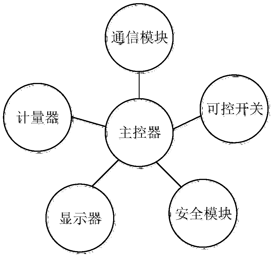
However, the smart meter with this structure still has a relatively large risk. When hackers maliciously attack and control the main controller, the security module cannot find that the data sent by the main controller is fake data, and cannot play a role in protecting data security. For example , after the main controller obtains the measurement value, the hacker tampers with the data and sends it to the security module for encryption and other security processing, and finally the main controller sends it to the main station through the communication module. It can be seen that in the whole process of data processing, The security module does not play a role in protecting the authenticity of the data, and the master station cannot find that the data has been tampered with during processing by the master controller; The security module verifies the validity of the command. The main controller will execute the power-off command after the command verification is passed. When the main controller is maliciously controlled, the main controller can skip the verification link and directly send a power-off signal to the controllable switch. , resulting in a malicious power-off situation
It can be seen that the security of the current smart meters is low, and the interests of users are easily violated.

Method used


Image

  • Smart electric meter
  • Smart electric meter
  • Smart electric meter

Examples


Embodiment Construction

[0034] The core of this application is to provide a smart meter, which avoids the risk of malicious tampering during processing by the main controller, improves the security of the meter, and better protects the interests of users.

[0035] In order to make the purposes, technical solutions and advantages of the embodiments of the present application clearer, the technical solutions in the embodiments of the present application will be clearly and completely described below in conjunction with the drawings in the embodiments of the present application. Obviously, the described embodiments It is a part of the embodiments of this application, not all of them. Based on the embodiments in this application, all other embodiments obtained by persons of ordinary skill in the art without making creative efforts belong to the scope of protection of this application.

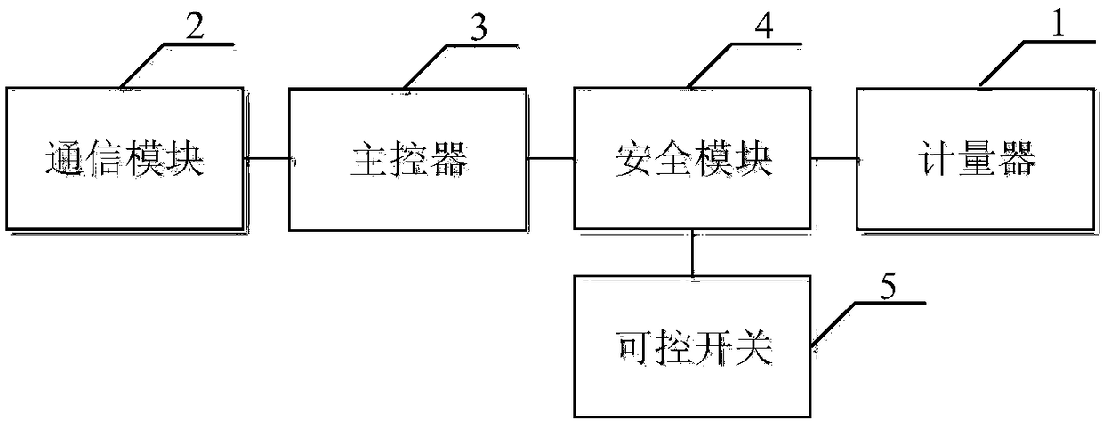
[0036] Please refer to figure 2 , figure 2 A schematic structural diagram of a smart meter provided by this applica...


PUM


Abstract

The application discloses a smart electric meter comprising a meter for measuring an electric quantity, a communication module for transmitting data, a main controller connected to the communication module, and a security module connected with the main controller and the meter respectively. The main controller is used for receiving data transmitted by a main station through the communication module, determining whether the data are metering sensitive data, if so, forwarding the data to the security module, and if not, performing a corresponding operation based on the data. The security moduleis used for carrying out a corresponding security operation on a metering value of the meter based on the metering sensitive data. According to the application, the metering sensitive data are processed directly by the security module; the security connected with the meter directly is able to carry out the security operation on the metering value of the meter directly; and thus the processing of the metering value is done by the security module with high security instead of the main controller, so that a risk of malicious tampering of the main controller during processing is eliminated. Therefore, the security of the electric meter is improved and the interests of the user are protected well.

Description

technical field [0001] The present application relates to the technical field of automated electronic products, in particular to a smart electric meter. Background technique [0002] The smart meter is the terminal of the smart grid. In addition to the basic power consumption measurement function of the traditional meter, it also has a variety of intelligent functions such as two-way multi-rate metering, user-side control, and anti-theft electricity. [0003] The structure of a common smart meter is as follows figure 1 As shown, including main controller, communication module, meter, safety module, display and controllable switch. The main controller performs corresponding operations under the control of the main station, such as reading the measurement value of the meter, controlling the controllable switch to close to realize power failure, etc., and the security module provides encryption for the main controller during the corresponding operation. Or decryption and othe...

Claims


Application Information

Patent Timeline
Patent Type & Authority Applications(China)
IPC IPC(8): G01R11/24
CPCG01R11/24
Inventor 杨祎巍林伟斌匡晓云崔超李舟
Owner ELECTRIC POWER RESEARCH INSTITUTE, CHINA SOUTHERN POWER GRID CO LTD
Learn More