
Switching power supply EMI test device and method

A technology of switching power supply and testing equipment, which is applied in the direction of power supply testing, measuring equipment, and components of electrical measuring instruments, to achieve the effects of improving the performance of the whole machine, saving rectification time and development costs, and reducing the amount of external emissions

Active Publication Date: 2018-11-23
GREE ELECTRIC APPLIANCES INC
View PDF2 Cites 5 Cited by
  • Summary
  • Abstract
  • Description
  • Claims
  • Application Information

AI Technical Summary

Problems solved by technology

[0003] Aiming at the above-mentioned problems existing in the prior art, the present invention provides a switching power supply EMI test device and method, which effectively solves the influence of the high-frequency transformer secondary loop electronic circuit on the EMI test in the switching power supply test, thereby separately evaluating the switching power supply itself EMI performance of the circuit

Method used


Image

  • Switching power supply EMI test device and method

Examples


Embodiment Construction

[0021] The present invention will be further described in detail below in conjunction with the drawings.

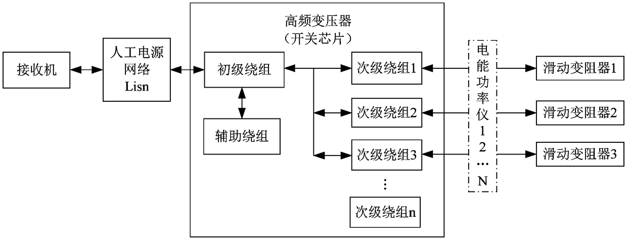
[0022] The circuit principle of the switching power supply EMI test device of the present invention is as follows figure 1 As shown, it includes a high-frequency transformer, a receiver, an artificial power supply network Lisn, an electric energy power meter, and a sliding rheostat. The high-frequency transformer is the device under test, and the high-frequency transformer includes a primary winding and several secondary windings. The machine, the artificial power supply network Lisn, the primary winding and the secondary winding are connected in sequence, and the secondary winding is connected to the sliding rheostat via an electric energy power meter. among them:

[0023] Receiver: a test instrument used to test high-frequency interference signals.

[0024] Artificial power supply network: signal isolation function, isolate external interference signals, the receiver only re...


PUM


Abstract

The present invention discloses a switching power supply EMI test device and method. The device comprises a high-frequency transformer, a receiver, an artificial mains network, an electric energy power instrument and a sliding slide rheostat, the high-frequency transformer comprises a primary winding and a plurality of secondary windings, the receiver, the artificial mains network, the primary winding and the secondary windings are connected in order, and the secondary windings is connected with the sliding slide rheostat through the electric energy power instrument. The switching power supplyEMI test device and method employ the secondary windings to connect with the sliding slide rheostat to replace a circuit, the sliding slide rheostat is a pure impedance device so as not to generate high-frequency components or have no interference or inhibition effect on the high-frequency components; the stability and the consistency of the performances of the switching power supply EMI are improved; the influences of the high-frequency transformer secondary loop electronic circuits in the switching power supply test on the EMI test are effectively solved so as to separately evaluate the performances of the EMI of the circuit of the switching power supply itself; and moreover, the external emission amount of the whole air conditioner is reduced to better improve the performances of the whole machine and save the rectification time and development cost.

Description

Technical field [0001] The invention relates to an interference test device and method, in particular to a switching power supply EMI test device and method. Background technique [0002] With the discovery of electronic technology, more and more control panel circuits will use switching power supplies for power conversion. With the development of chip technology, the switching frequency is getting higher and higher, and a lot of high-frequency interference will be generated. The current test method is to investigate the external interference EMI of the air conditioning machine. Generally speaking, the switching power supply works as a whole. In its operation, it is inevitable to use the secondary winding circuit of the second stage. The secondary winding of the switching power supply will be connected with diodes, voltage regulator blocks, capacitors, resistors, capacitors, and resistors. At work, it will have a certain inhibitory effect on high frequency signals, and at the s...

Claims


Application Information

Patent Timeline
Patent Type & Authority Applications(China)
IPC IPC(8): G01R31/40G01R1/20
CPCG01R1/203G01R31/40
Inventor 于洪涛肖彪万今明
Owner GREE ELECTRIC APPLIANCES INC
Learn More