[0035] The technical features of the present invention will be further described in detail below in conjunction with the accompanying drawings so that those skilled in the art can understand.
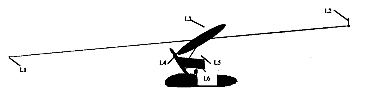
[0036] A horizontal off-axis three-reflection optical system for a vehicle-mounted head-up display device includes a light-emitting screen L6, a secondary reflector L5 is arranged obliquely in front of the light-emitting screen L6, and a main reflector is arranged obliquely in front of the secondary reflector L5. The reflecting mirror L4 and the windshield L3 are arranged above the main reflecting mirror L4.
[0037] in figure 1 As shown, the luminous screen L6 is the vehicle-mounted information required by the driver. The divergent light from the luminous screen L6 reaches the secondary reflector L5, and is reflected by the secondary reflector L5 to converge on the primary reflector L4. The light is reflected by the primary reflector L5. Displayed on the windshield L3, and then received by the entrance pupil (human eye) L2.
[0038] The invention achieves an ideal imaging effect through a reasonable angle offset, and makes the structure more compact, reduces the space occupied by the entire vehicle-mounted display device, and improves the customer's demand for the use of large space in the car.
[0039] As described above, for the horizontal off-axis three-reflection optical system of a vehicle-mounted head-up display device, the main reflector L4 is a concave reflector with positive refractive power and is made of plastic material; the secondary reflector L5 is non-focus Degree mirror.
[0040] In addition to the windshield, the present invention has only one optical element with optical power, which greatly reduces the processing cost, and the main reflector uses plastic materials, which also greatly saves the cost of raw materials. Compared with the HUD on the market, it has a strong cost advantage while ensuring the image quality.
[0041] As described above, for the horizontal off-axis three-mirror optical system of a vehicle-mounted head-up display device, the reflective surface of the main mirror L4 is a free-form surface of an XY polynomial, and satisfies the expression: 3500mm≤R 4 ≤3800mm, where R 4 The Y radius of the main mirror L4.
[0042] The invention uses a free-form surface for optimal design, and can better correct aberrations compared to other HUDs that use spherical surfaces for optimal design, and can achieve high-quality imaging effects with a small number of components.
[0043] The horizontal off-axis three-reflection optical system used in the vehicle head-up display device as described above, the optical system satisfies the expression: 65mm≤D 2 ≤80mm; Among them, D 2 It is the maximum offset of the entrance pupil L2 (human eye) relative to the optical axis on the XY plane, that is, the radius of the eye box that can be used.
[0044] The present invention achieves a larger eye box diameter compared with general HUDs in the market, that is, clear imaging images can be obtained when the human eyes move in this range, and solves the problem of unclear images of ordinary HUDs when the human body moves slightly.
[0045] As mentioned above, the horizontal off-axis three-mirror optical system used for vehicle head-up display device, when T 12 , T 23 When the change is within ±200mm at the same time, the MTF curve is good. Where T 12 Is the distance from the object plane L1 to the entrance pupil L2 on the optical axis; T 23 Is the distance from the entrance pupil L2 to the windshield L3 on the optical axis. T 12 And T 23 At the same time, changing a certain distance means that the human eye moves a certain distance back and forth. Therefore, when the speed of the vehicle changes and the body moves back and forth within ±200mm, the picture is still clear, so that a better use effect can be guaranteed during braking or speeding up.
[0046] As described above, the horizontal off-axis three-mirror optical system used in the vehicle head-up display device satisfies the expression:
[0047] 3°≤θ 2 ≤4.5°;
[0048] 3°≤θ 3 ≤4.5°;
[0049] Where θ 2 Is the offset of the entrance pupil L2 relative to the optical axis, θ 3 Is the offset of the windshield glass L3 relative to the optical axis. The design of this offset is designed to fit the human body characteristics during driving, and to simulate the human eye to ensure that the driver’s eye angle is consistent with the normal driving sight angle during use, and to improve the comfort and safety during use.
[0050] As described above, the horizontal off-axis three-mirror optical system used in the vehicle head-up display device satisfies the expression:
[0051] -4.5°≤α 45 ≤-3°;
[0052] 13°≤α 56 ≤16°;
[0053] Where α 45 The angle between the primary reflector L4 and the secondary reflector L5 in the α direction; α 56 It is the angle between the secondary mirror L5 and the light-emitting screen L6 in the α direction. The small angle control in the α direction can control the components in the same horizontal space, and there are fewer optical components in the present invention, and other components of the optical system except the windshield are in the same horizontal space, which greatly saves The space of the driver's cab satisfies customers' needs for the use of large space in the driver's cab.
[0054] In the present invention, nine different entrance pupil positions are set in the design process, as shown in Table 2 to Table 10 below, and the entrance pupil L2 is offset in the X and Y directions. Using this method to optimize the design ensures a larger eye box diameter and does not affect the sharpness of the imaging when the human body moves slightly.
[0055] Compared with other HUDs, this implementation has the following advantages:
[0056] 1. The diameter of the usable eye box can reach 130mm-160mm;
[0057] 2. When the distance T12 from the object plane L1 to the entrance pupil L2 on the optical axis and the distance from the entrance pupil L2 to the windshield L3 on the optical axis change at the same time, and the change range is within ±200mm, the MTF curve is good and the image is clear . That is, when the vehicle speed changes and the human body moves within ±200mm in the front and rear direction, it can ensure clear use and achieve the use effect of the zoom system; there are fewer optical components, cost-saving, and only one optical component except the windshield has light Focus, save processing costs, and have a strong cost advantage in market competition;
[0058] 3. In the design process, the characteristic of the optical path is horizontal. All the optical components except the windshield are controlled in the same horizontal space, which can save the space of the cab.
[0059] The following is a parameter table of the embodiment of the present invention.
[0060] Table 1 below shows the structural parameters of the invention:
[0061] Surface number
[0062] Table 1
[0063] Table 2 below shows the eccentricity setting parameters of the present invention when the entrance pupil is at position 1:
[0064]
[0065] Table 2
[0066] Table 3 below shows the eccentricity setting parameters of the present invention when the entrance pupil is at position 2:
[0067]
[0068] table 3
[0069] The following table 4 shows the eccentricity setting parameters when the entrance pupil of the present invention is at position 3:
[0070]
[0071] Table 4
[0072] Table 5 below shows the eccentricity setting parameters of the present invention when the entrance pupil is at position 4:
[0073]
[0074] table 5
[0075] Table 6 below shows the eccentricity setting parameters when the entrance pupil is at position 5 of the present invention:
[0076]
[0077] Table 6
[0078] Table 7 below shows the eccentricity setting parameters of the present invention when the entrance pupil is at position 6:
[0079]
[0080] Table 7
[0081] The following table 8 shows the eccentric setting parameters of the present invention when the entrance pupil is at position 7:
[0082]
[0083] Table 8
[0084] Table 9 below shows the eccentricity setting parameters when the entrance pupil is at position 8 of the present invention:
[0085]
[0086] Table 9
[0087] Table 10 below shows the eccentricity setting parameters of the present invention when the entrance pupil is at position 9:
[0088]
[0089] Table 10
[0090] The embodiments of the present invention are only descriptions of the preferred embodiments of the present invention, and do not limit the concept and scope of the invention. Under the premise of not departing from the design concept of the present invention, those skilled in the art have an understanding of the technical solutions of the present invention. Various modifications and improvements made should fall within the protection scope of the present invention.