
Permanent magnet motor and control method and system for same

A permanent magnet motor and control module technology, which is applied in the field of geological exploration, can solve the problems that the motor cannot meet the three power demand environments at the same time, the constant power range of the motor is narrow, and the high-efficiency area is narrow, and the effect of energy-saving vehicle power output is achieved.

Active Publication Date: 2018-11-23
HUNAN CSR TIMES ELECTRIC VEHICLE
View PDF6 Cites 4 Cited by
  • Summary
  • Abstract
  • Description
  • Claims
  • Application Information

AI Technical Summary

Problems solved by technology

[0004] However, in the prior art, due to the structural problems of the motor itself, the motor has the problems of narrow constant power range and narrow high efficiency range (only one peak efficiency range)
This makes it impossible for the same motor to meet the three power demand environments at the same time

Method used


Image

  • Permanent magnet motor and control method and system for same
  • Permanent magnet motor and control method and system for same
  • Permanent magnet motor and control method and system for same

Examples


Embodiment Construction

[0046] The implementation of the present invention will be described in detail below in conjunction with the accompanying drawings and examples, so that implementers of the present invention can fully understand how the present invention uses technical means to solve technical problems, and achieve the realization process of technical effects and according to the above-mentioned realization process The present invention is implemented concretely. It should be noted that, as long as there is no conflict, each embodiment and each feature in each embodiment of the present invention can be combined with each other, and the formed technical solutions are all within the protection scope of the present invention.

[0047] With the continuous development of electric motor technology, more and more vehicles use electric motors as power.

[0048] In actual application scenarios, the power demand of the same vehicle is not limited to one application scenario. For example, the power dema...


PUM


Abstract

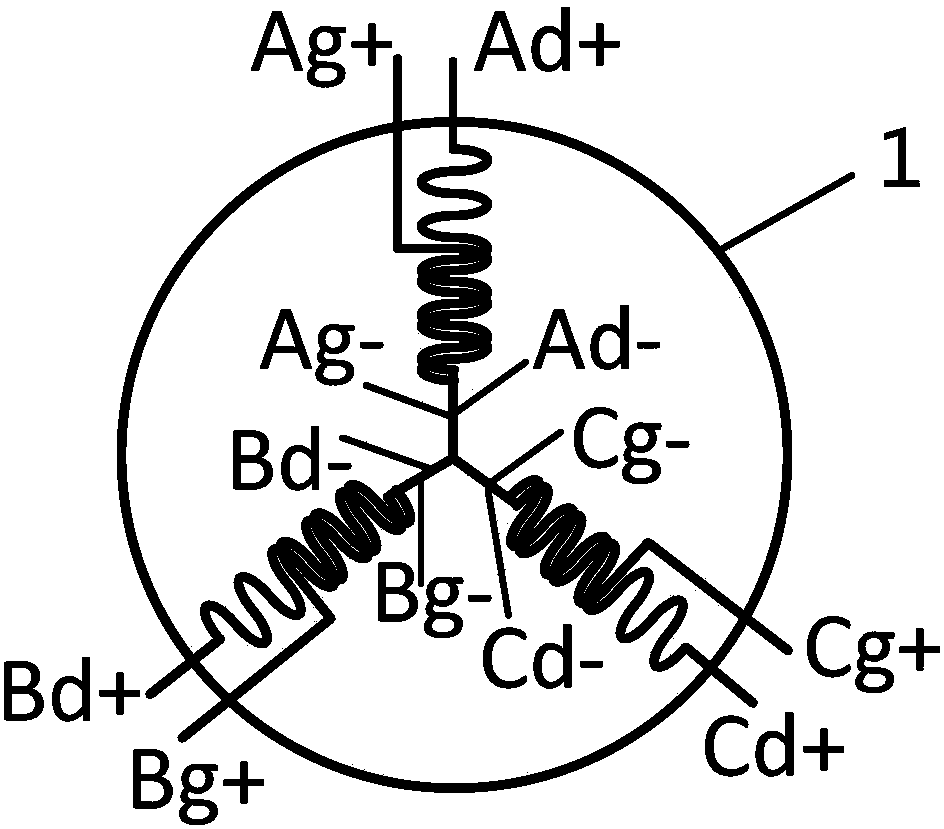
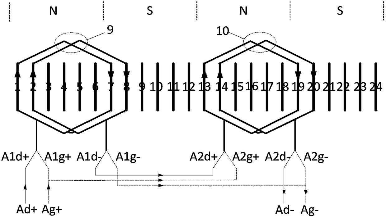
The invention discloses a permanent magnet motor and a control method and system for the same. Each phase of the permanent magnet motor comprises low-speed windings and high-speed windings, wherein the low-speed windings of different phases are equal in number of turns and the high-speed windings of different phases are equal in number of turns; and the number of turns per phase in series for thelow-speed windings is greater than that of the high-speed windings in the same phase. According to permanent magnet motor disclosed by the invention, three different drive modes can be provided to bematched with vehicle power demands of different application scenarios. Compared with the prior art, the permanent magnet motor, the control method for the motor and the control system for the motor have the advantage more efficient and energy-efficient vehicle power output can be achieved.

Description

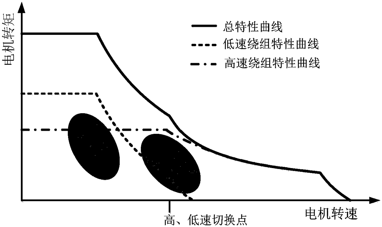
technical field [0001] The invention relates to the field of geological exploration, in particular to a permanent magnet motor and a control method and system for the motor. Background technique [0002] With the continuous development of electric motor technology, more and more vehicles use electric motors as power. [0003] In actual application scenarios, the power demand of the same vehicle is not limited to one application scenario. For example, the power demand of a vehicle can generally be divided into three scenarios: low speed and light load, high speed (low load) operation, and low speed and heavy load. That is, the vehicle has requirements for low-speed high-torque, high-speed constant power and wide-range high-efficiency areas for the power system. The most ideal power matching mode is to enable the power system to have three driving states at the same time to match the above three scenarios respectively. [0004] However, in the prior art, due to the structur...

Claims


Application Information

Patent Timeline
Patent Type & Authority Applications(China)
IPC IPC(8): H02K3/28H02K3/12H02P25/18
CPCH02K3/12H02K3/28H02P25/18
Inventor 成双银刘凌王征宇杨洪波王坤俊郭淑英彭俊
Owner HUNAN CSR TIMES ELECTRIC VEHICLE
Learn More