
Dead zone compensation method, device, system, and drive controller

A drive controller and dead zone compensation technology, applied in the direction of AC motor control, motor vibration suppression control, control system, etc., can solve the problems of reducing motor performance, motor output waveform distortion, etc., to avoid current distortion, stable and reliable operation, The effect of avoiding motor speed fluctuations

Pending Publication Date: 2018-11-23
GREE ELECTRIC APPLIANCES INC
View PDF0 Cites 2 Cited by
  • Summary
  • Abstract
  • Description
  • Claims
  • Application Information

AI Technical Summary

Problems solved by technology

[0004] Embodiments of the present invention provide a dead zone compensation method, device and system, and a drive controller to solve the problem in the prior art that the dead zone time causes distortion of the output waveform of the motor and reduces the performance of the motor

Method used


Image

  • Dead zone compensation method, device, system, and drive controller
  • Dead zone compensation method, device, system, and drive controller
  • Dead zone compensation method, device, system, and drive controller

Examples


Embodiment Construction

[0056] The present invention will be further described in detail below in conjunction with the accompanying drawings and specific embodiments. It should be understood that the specific embodiments described here are only used to explain the present invention, and are not intended to limit the present invention.

[0057] In the following description, use of suffixes such as 'module', 'part' or 'unit' for denoting elements is only for facilitating description of the present invention and has no specific meaning by itself. Therefore, 'module', 'part' or 'unit' may be used in combination.

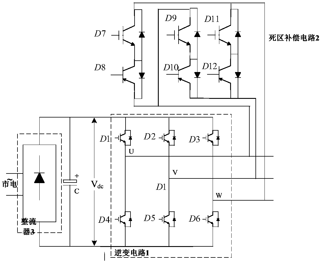
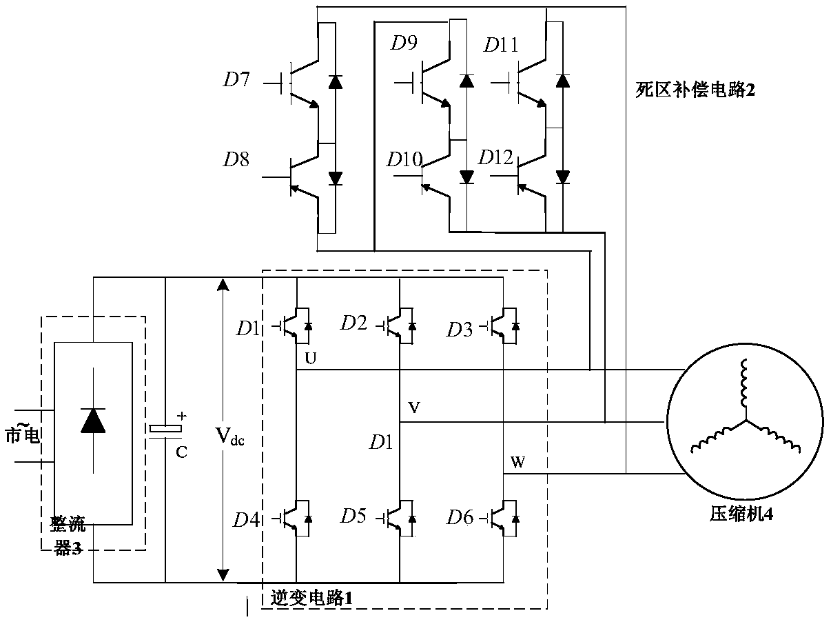
[0058] In order to solve the problem in the prior art that the output waveform of the motor is distorted and the performance of the motor is reduced due to the dead time, the embodiment of the present invention provides a drive controller, such as figure 1 As shown, the drive controller includes: an inverter circuit 1 and a dead zone compensation circuit 2 .

[0059] The dead zone compensation...


PUM


Abstract

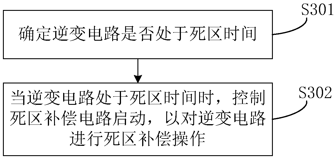
The invention discloses a dead zone compensation method, a device, a system and a drive controller. The system comprises a motor and a drive controller, wherein a dead zone compensation circuit is connected with the motor, the drive controller is used for determining whether a inverter circuit is in a dead time. When the inverter circuit is in the dead zone time, a starting signal is sent to the dead zone compensation circuit; the dead zone compensation circuit is used for receiving the starting signal, so as to perform a dead zone compensation operation on the inverter circuit. According to the dead zone compensation method, the device, the system, and the drive controller, the motor can be a compressor, the voltage output from the inverter circuit to the motor zero during the dead time can be zero, so as to ensure that the voltage output to the motor is consistent with the expected voltage value of PWM during modulation. The current distortion caused by waveform distortion and the fluctuation of the motor speed are avoided, so that the operation of the motor is more stable and reliable, and the noise is small.

Description

technical field [0001] The invention relates to the technical field of motor control, in particular to a dead zone compensation method, device and system, and a drive controller. Background technique [0002] In the field of compressors, a PWM (Pulse Width Modulation, pulse width modulation) method is usually used to control the voltage output to the compressor. That is, each bridge arm switch tube is turned on or off alternately to obtain a desired voltage or current. However, since the switch tube is turned on and off with a certain delay, it takes a certain amount of time. In order to prevent the upper and lower switching tubes of the same bridge arm from being turned on at the same time, a dead time is usually provided. Although the dead time is at the microsecond level, with the accumulation of time, the dead time will generate an inestimable counter electromotive force, resulting in a deviation between the actual output voltage value and the expected voltage value, c...

Claims


Application Information

Patent Timeline
Patent Type & Authority Applications(China)
IPC IPC(8): H02P23/04H02P27/08H02M7/5395H02M7/5387
CPCH02M7/5387H02M7/5395H02P23/04H02P27/08
Inventor 贺小林刘文斌刘涛
Owner GREE ELECTRIC APPLIANCES INC
Learn More