Method and furnace installation for heat treating metal strip

A technology for metal strips and heating furnaces, applied in heat treatment equipment, lighting and heating equipment, heat treatment furnaces, etc., can solve the problems of short residence time of internal oxidation and adverse effects on product quality.

Active Publication Date: 2018-11-23
ANDRITZ TECH & ASSET MANAGEMENT
View PDF2 Cites 0 Cited by
  • Summary
  • Abstract
  • Description
  • Claims
  • Application Information

AI Technical Summary

Problems solved by technology

[0007] However, in the case of conventional direct-fired furnaces or at high production rates, the residence time for internal oxidation is very short, which can have a detrimental effect on product quality

Method used


Image

  • Method and furnace installation for heat treating metal strip
  • Method and furnace installation for heat treating metal strip

Examples


Embodiment Construction

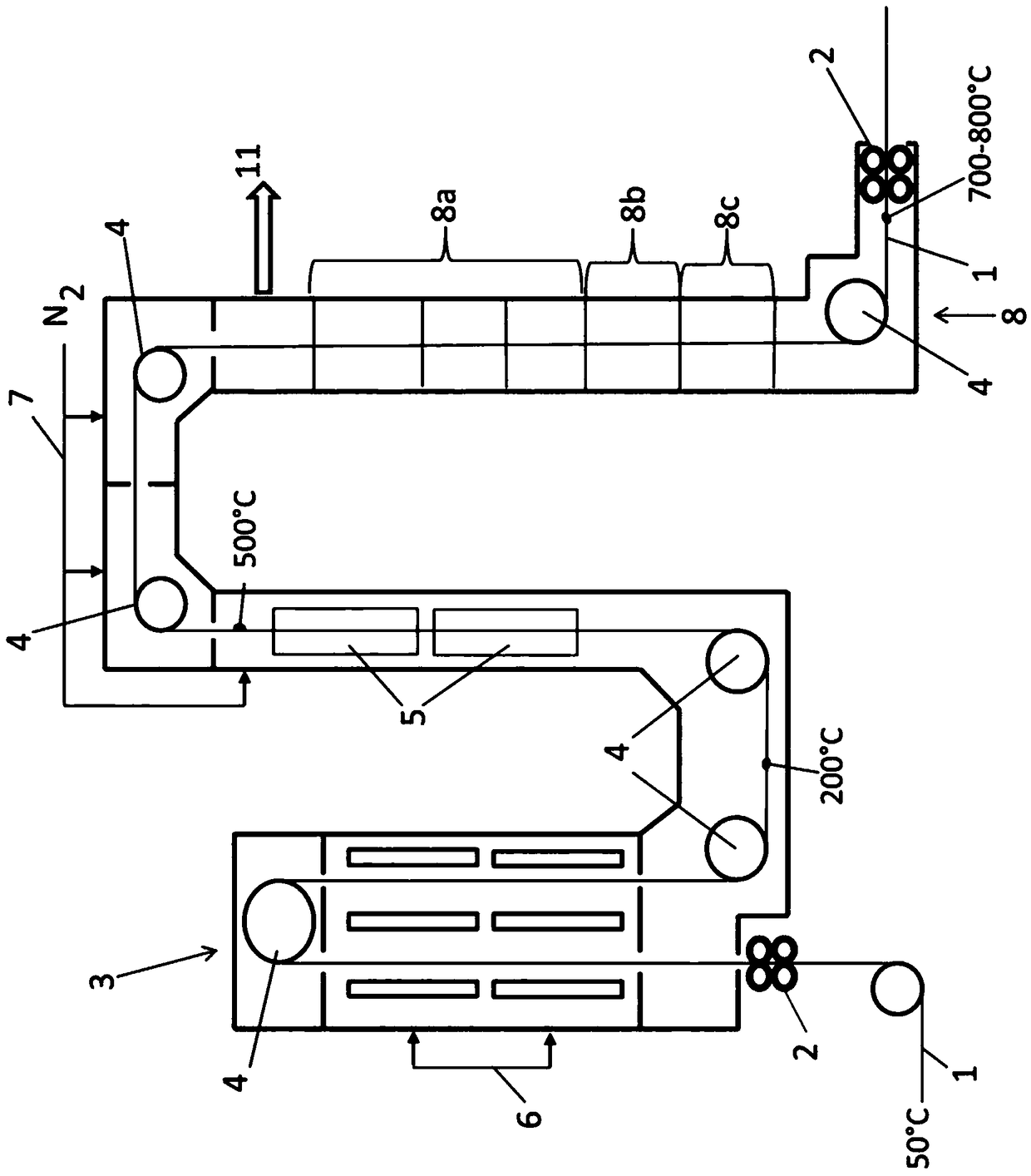
[0021] exist figure 1 At an entry temperature of approximately 50° C., the metal strip 1 passes through the pair of sealing rollers 2 continuously into the preheating zone 3 of the furnace installation and is heated there by means of hot nitrogen 6 to approximately 200° C. Hot nitrogen gas 6 is blown directly onto the metal strip 1 through nozzles. Turning rollers 4 guide the metal strip 1 through the furnace arrangement. Adjoining the preheating zone 3 , the metal strip 1 is further heated to approximately 500° C. in a protective gas atmosphere by means of an induction heater 5 . Nitrogen is also fed into this zone via line 7 . The metal strip then enters a direct-fired furnace 8, where the metal strip 1 is further heated in the starting zone 8a, and then the metal strip is stripped of the oxide layer in a reducing atmosphere at about 720° C. in the reducing zone 8b. Next, the metal strip 1 from which the oxide layer has been removed is subjected to an oxidizing atmosphere...


PUM


Abstract

The subject matter of this invention is a method for the heat treatment of a metal strip (1), wherein the metal strip (1) is continuously preheated with the aid of hot gas (6) in a preheating zone (3)and subsequently further heat-treated in a reducing and / or oxidizing atmosphere in a directly fired furnace. According to the invention, the metal strip (1) is preheated in the preheating zone (3) byhot shielding gas (6), and before it enters the directly fired furnace (8) is heated further with an electrical heating system (5). The subject matter of this invention is also a furnace installationfor carrying out the method according to the invention.

Description

technical field [0001] The invention relates to a method for the heat treatment of metal strips, wherein the metal strip is preheated by means of hot gases in a preheating zone and then treated in a direct fired furnace in a reducing and / or oxidizing atmosphere The metal strip undergoes further heat treatment. The invention also relates to a furnace installation for carrying out the method of the invention. Background technique [0002] The heat treatment of the metal strip is usually carried out before the galvanizing of the metal strip, or also after the pickling line in an annealing furnace. [0003] One possibility for heat treatment is to use a direct fired furnace (DFF), in which the burners are arranged directly within the furnace interior. In this furnace there is a preheating zone in which the metal strip, which is continuously led through, is preheated to approximately 200 to 300° C. by means of hot gases from the directly fired furnace. Before the heat treatmen...

Claims


Application Information

Patent Timeline
Patent Type & Authority Applications(China)
IPC IPC(8): C21D1/74C21D9/56C21D9/60F27B9/04F27B9/12
CPCC21D1/74C21D9/561C22F1/02F27B9/045F27B9/06C21D1/42C21D9/60F27B9/047F27B9/067F27B9/28F27B9/36F27D17/004F27B9/12Y02P10/25
Inventor 皮埃尔-热鲁姆·博赫勒埃里克·布雷克
Owner ANDRITZ TECH & ASSET MANAGEMENT
Why Eureka
Try Eureka